Toyota 4Runner: Power Source Control ECU Malfunction (B2782)
DESCRIPTION
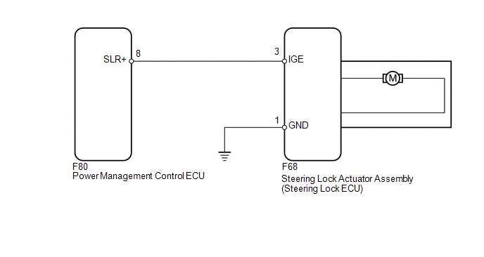
The steering lock ECU activates the steering lock motor with the power from the power management control ECU through the IGE circuit. This prevents the steering from being locked while the vehicle is moving.
If NG (PAST) is displayed for Power Supply Open in the Data List, perform troubleshooting according to the procedures below.
The diagnosis information of the steering lock ECU is transmitted to the Techstream via the certification ECU as the steering lock actuator assembly (steering lock ECU) is not connected to the CAN communication system.
|
DTC Code |
Detection Condition |
Trouble Area |
|---|---|---|
|
B2782 |
An IGE power supply circuit malfunction. |
|
WIRING DIAGRAM
CAUTION / NOTICE / HINT
HINT:
When the engine switch is off, the main body ECU may occasionally go into a non-active state called sleep mode. Therefore, before proceeding with the inspection, it is necessary to perform the following steps to wake up the ECU:
With the engine switch off, open the driver door. Then (with the engine switch still off) open and close any door several times at 1.5 second intervals.
NOTICE:
- When disconnecting the cable from the negative (-) battery terminal,
some systems need to be initialized after the cable is reconnected (See
page
.gif) ).
). - If the steering lock actuator assembly (steering lock ECU) is replaced, with the engine switch off and the shift lever in P, open and close the driver side door to record the current lock position into the steering lock ECU. If this is not performed, the engine may not start.
- When replacing the steering lock ECU, registration must be performed
(See page ).
PROCEDURE
|
1. |
INSPECT STEERING LOCK ECU |
|
(a) Disconnect the F68 steering lock ECU connector. |
|
.png)
(b) Turn the engine switch off, make sure that the steering lock is unlocked and move the shift lever to P.
(c) Measure the resistance according to the value(s) in the table below.
Standard Resistance:
|
Tester Connection |
Condition |
Specified Condition |
|---|---|---|
|
F68-1 (GND) - Body ground |
Always |
Below 1 Ω |
|
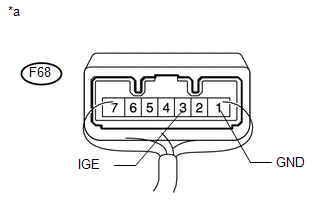
*a |
Front view of wire harness connector (to Steering Lock ECU) |
|
(d) Reconnect the F68 steering lock ECU connector. |
|
(e) Measure the voltage according to the value(s) in the table below.
Standard Voltage:
|
Tester Connection |
Condition |
Specified Condition |
|---|---|---|
|
F68-3 (IGE) - F68-1 (GND) |
Driver side door opened |
Below 1 V (Steering lock motor operating) |
|
F68-3 (IGE) - F68-1 (GND) |
Driver side door opened |
11 to 14 V (Steering lock motor not operating) |
HINT:
When the steering lock is locked and the engine is switch is turned on (IG), the steering lock motor activates to release the steering lock. The motor operates for 2 to 15 seconds.
Text in Illustration|
*a |
Component with harness connected (Steering Lock ECU) |
| NG | .gif) |
GO TO STEP 4 |
|
.gif)
|
2. |
CLEAR DTC |
(a) Clear the DTCs (See page ).
(b) Disconnect and reconnect the cable to the negative (-) battery terminal to clear the malfunction history of Power Supply Open.
|
|
3. |
READ VALUE USING TECHSTREAM (POWER SUPPLY OPEN) |
(a) Check for DTCs (See page ).
(b) Use the Data List to check if the steering lock control is functioning properly.
Smart Key|
Tester Display |
Measurement Item/Range |
Normal Condition |
Diagnostic Note |
|---|---|---|---|
|
Power Supply Open |
Open in ECU record/NG (PAST) or OK |
NG (PAST): Open in ECU OK: No malfunction |
- |
|
Result |
Proceed to |
|---|---|
|
A |
|
B |
| A | |
USE SIMULATION METHOD TO CHECK |
| B | |
REPLACE STEERING LOCK ACTUATOR ASSEMBLY (STEERING LOCK ECU) |
|
4. |
CHECK HARNESS AND CONNECTOR (STEERING LOCK ECU - POWER MANAGEMENT CONTROL ECU) |
(a) Disconnect the F80 power management control ECU connector.
(b) Disconnect the F68 steering lock ECU connector.
(c) Measure the resistance according to the value(s) in the table below.
Standard Resistance:
|
Tester Connection |
Condition |
Specified Condition |
|---|---|---|
|
F68-3 (IGE) - F80-8 (SLR+) |
Always |
Below 1 Ω |
|
F68-3 (IGE) or F80-8 (SLR+) - Body ground |
Always |
10 kΩ or higher |
| OK | |
REPLACE POWER MANAGEMENT CONTROL ECU |
| NG | |
REPAIR OR REPLACE HARNESS OR CONNECTOR |
 IG2 Signal Malfunction (B2788)
DESCRIPTION
The steering lock ECU determines the on/off status of the engine switch through
the IG2 signal circuit.
The steering lock ECU does not lock the steering when it receives the IG2 relay ...
 Open / Short in Steering Lock ECU (B2781)
DESCRIPTION
The steering lock ECU and steering lock actuator assembly are supplied as a unit.
The steering lock ECU detects the steering lock position through the signals
from the lock and unlock ...
Other materials about Toyota 4Runner:
Power Mirror Control System
Precaution
PRECAUTION
1. IGNITION SWITCH EXPRESSION
HINT:
The type of ignition switch used on this model differs according to the specifications
of the vehicle. The expressions listed in the table below are used in this section.
Expression
...
Problem Symptoms Table
PROBLEM SYMPTOMS TABLE
HINT:
Use the table below to help determine the cause of problem symptoms.
If multiple suspected areas are listed, the potential causes of the symptoms
are listed in order of probability in the "Suspected Area" ...

0.0083