Toyota 4Runner: Inspection
INSPECTION
PROCEDURE
1. INSPECT TIE ROD END SUB-ASSEMBLY
|
(a) Install the nut. |
|
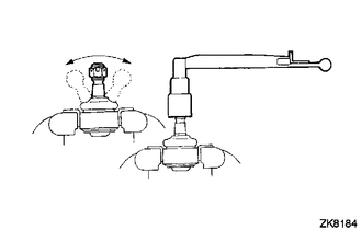
(b) Flip the ball joint stud back and forth 5 times as shown in the illustration.
(c) Using a torque wrench, turn the nut continuously at a rate of 3 to 5 seconds per turn and check the torque reading on the 5th turn.
Standard Torque:
1.0 to 3.9 N*m (10 to 39 kgf*cm, 9 to 34 in.*lbf)
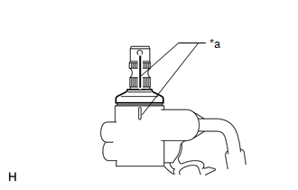
2. INSPECT TOTAL PRELOAD
|
(a) Place matchmarks as shown in the illustration. Text in Illustration
|
|
(b) Temporarily install the 2 steering rack ends to the steering rack.
NOTICE:
Do not fully turn the steering rack without the steering rack ends installed as it may damage the oil seal in the rack housing.
|
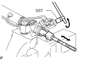
(c) Using SST, fully turn the steering rack right and left 10 times to settle it. SST: 09616-00011 |
|
|
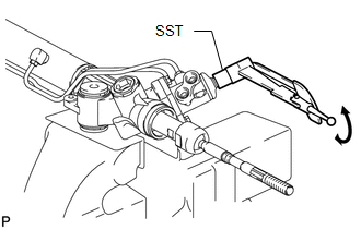
(d) Using SST, turn the control valve and measure the preload. SST: 09616-00011 Standard preload (turning): 1.6 to 2.3 N*m (16 to 23 kgf*cm, 14 to 20 in.*lbf) If the turning torque is not as specified, replace the steering gear assembly. HINT:
|
|
(e) After inspecting the preload, align the matchmarks.
 Disassembly
DISASSEMBLY
CAUTION / NOTICE / HINT
NOTICE:
When using a vise, do not overtighten it.
PROCEDURE
1. REMOVE TIE ROD END SUB-ASSEMBLY LH
(a) Put matchmarks on the tie rod end LH and stee ...
 Reassembly
REASSEMBLY
PROCEDURE
1. INSTALL STEERING RACK END SUB-ASSEMBLY
(a) Temporarily install the 2 steering rack ends to the steering rack.
(b) Fill up the ball joints of the steering rack ends with MP ...
Other materials about Toyota 4Runner:
On-vehicle Inspection
ON-VEHICLE INSPECTION
CAUTION / NOTICE / HINT
HINT:
Use the same procedure for the RH and LH sides.
The procedure listed below is for the LH side.
PROCEDURE
1. CHECK SIDE AIRBAG SENSOR ASSEMBLY LH (VEHICLE NOT INVOLVED IN COLLISION)
(a) ...
Using the Bluetooth® audio system
Audio unit
1. Display Track title, Artist name, Album name, Elapsed time, “Streaming
Audio”, etc. is displayed.
2. Selects items such as menu and number Turn: Selects an item Press: Inputs the
selected item 3. Bluetooth-Audio connection condition I ...

0.0068