Toyota 4Runner: Disassembly
DISASSEMBLY
CAUTION / NOTICE / HINT
NOTICE:
When using a vise, do not overtighten it.
PROCEDURE
1. REMOVE TIE ROD END SUB-ASSEMBLY LH
|
(a) Put matchmarks on the tie rod end LH and steering rack end. Text in Illustration
|
|
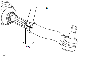
(b) Measure length A and record the measurement.
(c) Remove the tie rod end LH.
2. REMOVE TIE ROD END SUB-ASSEMBLY RH
HINT:
Use the same procedures described for the LH side.
3. REMOVE TURN PRESSURE TUBE
|
(a) Using a union nut wrench, remove the turn pressure tube LH and RH. |
|
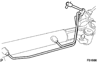
4. REMOVE STEERING GEAR OUTLET RETURN TUBE
|
(a) Using a union nut wrench, remove the return tube from the steering gear. |
|
5. REMOVE STEERING RACK BOOT CLIP LH
(a) Using pliers, remove the steering rack boot clip.
6. REMOVE STEERING RACK BOOT CLIP RH
HINT:
Use the same procedures described for the LH side.
7. REMOVE STEERING RACK BOOT CLAMP LH
(a) Using pliers, remove the boot clamp as shown in the illustration.
NOTICE:
Be careful not to damage the steering rack boot.
8. REMOVE STEERING RACK BOOT CLAMP RH
HINT:
Use the same procedures described for the LH side.
9. REMOVE NO. 2 STEERING RACK BOOT
(a) Remove the steering rack boot.
10. REMOVE NO. 1 STEERING RACK BOOT
(a) Remove the steering rack boot.
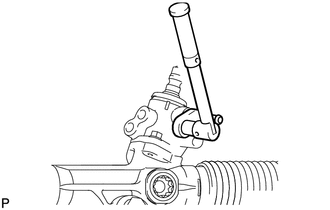
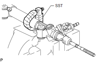
11. SECURE RACK AND PINION POWER STEERING GEAR ASSEMBLY
|
(a) Using SST, secure the steering gear assembly. SST: 09612-00012 HINT: Tape SST before use. |
|
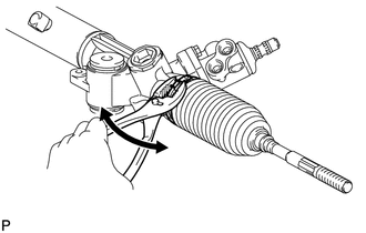
12. REMOVE STEERING RACK END SUB-ASSEMBLY
|
(a) Using SST, hold the steering rack (LH side). SST: 09922-10010 Text in Illustration
|
|
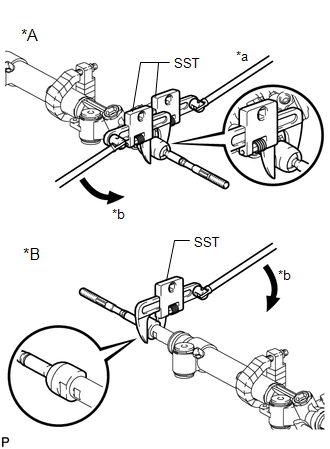
(b) Using SST, remove the steering rack end (LH side) from the steering rack.
SST: 09922-10010
HINT:
Rotate SST in the direction shown in the illustration.
(c) Using SST, remove the steering rack end (RH side) from the steering rack.
SST: 09922-10010
HINT:
Rotate SST in the direction shown in the illustration.
NOTICE:
- Be sure to rotate SST in the correct direction.
- Be sure to keep the steering rack fixed in place with SST.
 Removal
REMOVAL
PROCEDURE
1. PLACE FRONT WHEELS FACING STRAIGHT AHEAD
2. REMOVE FRONT WHEELS
3. REMOVE NO. 1 ENGINE UNDER COVER SUB-ASSEMBLY
Click here
4. REMOVE REAR ENGINE UNDER COVER ASSEMBLY
Clic ...
 Inspection
INSPECTION
PROCEDURE
1. INSPECT TIE ROD END SUB-ASSEMBLY
(a) Install the nut.
(b) Flip the ball joint stud back and forth 5 times as shown in t ...
Other materials about Toyota 4Runner:
On-vehicle Inspection
ON-VEHICLE INSPECTION
PROCEDURE
1. INSPECT REFRIGERANT PRESSURE WITH MANIFOLD GAUGE SET
(a) This method uses a manifold gauge set to locate problem areas. Read the manifold
gauge pressure when these conditions are established.
Test conditions:
Te ...
Disposal
DISPOSAL
CAUTION / NOTICE / HINT
CAUTION:
Before performing pre-disposal deployment of any SRS part, review and closely
follow all applicable environmental and hazardous material regulations. Pre-disposal
deployment may be considered hazardous material ...

0.0121