Toyota 4Runner: Inspection
INSPECTION
PROCEDURE
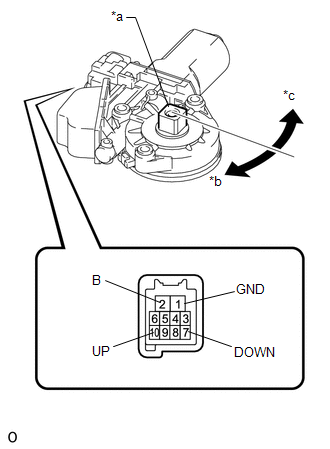
1. INSPECT BACK DOOR POWER WINDOW REGULATOR MOTOR ASSEMBLY
|
(a) Check that the motor gear rotates smoothly as follows. NOTICE: Do not apply positive (+) battery voltage to any terminals except terminal 2 (B) to avoid damaging the pulse sensor inside the motor. OK:
CAUTION: Reset the power window regulator motor (initialize the pulse sensor) after installing the power window regulator motor and regulator assembly to the door. Text in Illustration
|
|
 Removal
REMOVAL
PROCEDURE
1. DISCONNECT CABLE FROM NEGATIVE BATTERY TERMINAL
CAUTION:
Wait at least 90 seconds after disconnecting the cable from the negative (-)
battery terminal to disable the SRS sys ...
 Installation
INSTALLATION
PROCEDURE
1. INSTALL BACK DOOR POWER WINDOW REGULATOR MOTOR ASSEMBLY
(a) Using a T25 "TORX" socket wrench, install the back power window regulator
motor assemb ...
Other materials about Toyota 4Runner:
Compass
The compass on the accessory meter display indicates the direction in
which the vehicle is heading.
1. “MODE/ ” button
2. “SET/ ” button
3. Direction display
Displays and directions
Calibrating the compass
The direction display deviates ...
Removal
REMOVAL
PROCEDURE
1. REMOVE ASSIST STRAP HOLE COVER
2. REMOVE ASSIST STRAP ASSEMBLY
3. REMOVE BACK DOOR TRIM PANEL ASSEMBLY
4. REMOVE MULTIPLEX NETWORK DOOR ECU
5. REMOVE NO. 2 BACK DOOR SERVICE HOLE COVER
6. REMOVE BACK DOOR LOCK CYLINDE ...

0.0072