Toyota 4Runner: Removal
REMOVAL
PROCEDURE
1. DISCONNECT CABLE FROM NEGATIVE BATTERY TERMINAL
CAUTION:
Wait at least 90 seconds after disconnecting the cable from the negative (-) battery terminal to disable the SRS system.
NOTICE:
When disconnecting the cable, some systems need to be initialized after the cable
is reconnected (See page .gif) ).
).
2. REMOVE DOOR SCUFF PLATE ASSEMBLY RH
|
(a) Put protective tape around the door scuff plate. Text in Illustration
|
|
.png)
(b) Using a screwdriver, detach the 4 clips, 10 claws and 2 guides and remove the door scuff plate.
HINT:
Tape the screwdriver tip before use.
3. REMOVE COWL SIDE TRIM BOARD RH
|
(a) Remove the clip. |
|
.png)
(b) Detach the clip and claw and remove the cowl side trim board.
4. REMOVE NO. 2 INSTRUMENT CLUSTER FINISH PANEL GARNISH
(a) Open the instrument cluster finish panel lid.
(b) Put protective tape around the No. 2 instrument cluster finish panel garnish.
(c) Grip the No. 2 instrument cluster finish panel garnish and pull it diagonally upward toward the rear to detach the 5 clips and remove the No. 2 instrument cluster finish panel garnish.
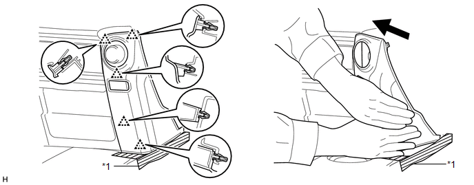 Text in Illustration
|
*1 |
Protective Tape |
- |
- |
5. REMOVE NO. 2 INSTRUMENT PANEL UNDER COVER SUB-ASSEMBLY
6. REMOVE LOWER INSTRUMENT COVER LH
7. REMOVE LOWER NO. 2 INSTRUMENT PANEL AIRBAG ASSEMBLY
8. REMOVE INSTRUMENT PANEL BOX DOOR COVER
9. REMOVE LOWER INSTRUMENT PANEL SUB-ASSEMBLY
10. REMOVE NO. 2 AIR DUCT SUB-ASSEMBLY
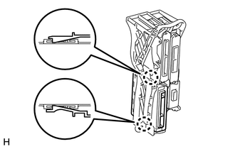
11. REMOVE ECU INTEGRATION BOX RH
.png)
(a) Disconnect the connectors and detach the clamp.
(b) Remove the 2 nuts, bolt and ECU integration box RH.
12. REMOVE AIR CONDITIONING AMPLIFIER ASSEMBLY
(a) Detach the 2 claws and remove the air conditioning amplifier assembly.
 Installation
INSTALLATION
CAUTION / NOTICE / HINT
HINT:
A bolt without a torque specification is shown in the standard bolt chart (See
page ).
PROCEDURE
1. INSTALL AIR CONDITIONER AMPLIFIER ASSEMBLY
(a) A ...
 Air Conditioning Panel
Components
COMPONENTS
ILLUSTRATION
Installation
INSTALLATION
PROCEDURE
1. INSTALL HEATER CONTROL ASSEMBLY
(a) Attach the 4 clips to install the heater control assembly.
...
Other materials about Toyota 4Runner:
Removal
REMOVAL
PROCEDURE
1. REMOVE FRONT BUMPER COVER (w/o Intuitive Parking Assist System)
(See Page )
2. REMOVE FRONT BUMPER COVER (w/ Intuitive Parking Assist System)
(See Page )
3. REMOVE HIGH PITCHED HORN ASSEMBLY
4. REMOVE RADIATOR GRILLE BRACKET
...
Installation with LATCH system (rear/second row seats only)
Installing on the rear seats (vehicles without third row seats)
Fold the seatback while pulling the seatback angle adjustment lever. Return
the seatback and secure it at the first lock position.
Type A
Latch the hooks of the lower straps onto the LATC ...

0.0081