Toyota 4Runner: Inspection
INSPECTION
PROCEDURE
1. INSPECT FRONT DOOR LOCK ASSEMBLY LH
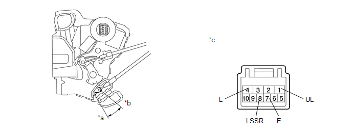
(a) Check the door lock motor operation.
(1) Apply battery voltage to the motor connector and check the operation of the door lock.
 Text in Illustration
|
*a |
Lock |
*b |
Unlock |
|
*c |
Component without harness connected (Front Door Lock Assembly LH) |
- |
- |
OK:
|
Measurement Condition |
Specified Condition |
|---|---|
|
Battery positive (+) → 4 (L) Battery negative (-) → 1 (UL) |
Lock |
|
Battery positive (+) → 1 (UL) Battery negative (-) → 4 (L) |
Unlock |
- If the result is not as specified, replace the front door lock assembly.
(b) Check the detection switch.
(1) Measure the resistance according to the value(s) in the table below.
Standard Resistance:
|
Tester Connection |
Switch Condition |
Specified Condition |
|---|---|---|
|
8 (LSSR) - 7 (E) |
Lock |
10 kΩ or higher |
|
8 (LSSR) - 7 (E) |
Unlock |
Below 1 Ω |
- If the result is not as specified, replace the front door lock assembly.
(c) Check the door lock and unlock switch.
(1) Measure the resistance according to the value(s) in the table below.
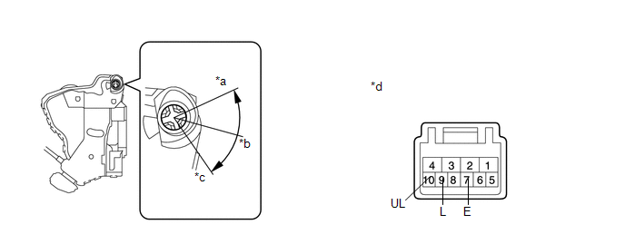 Text in Illustration
|
*a |
Lock |
*b |
Off |
|
*c |
Unlock |
*d |
Component without harness connected (Front Door Lock Assembly LH) |
Standard Resistance:
|
Tester Connection |
Switch Condition |
Specified Condition |
|---|---|---|
|
9 (L) - 7 (E) |
Lock |
Below 1 Ω |
|
9 (L) - 7 (E) 10 (UL) - 7 (E) |
Off |
10 kΩ or higher |
|
10 (UL) - 7 (E) |
Unlock |
Below 1 Ω |
- If the result is not as specified, replace the front door lock assembly.
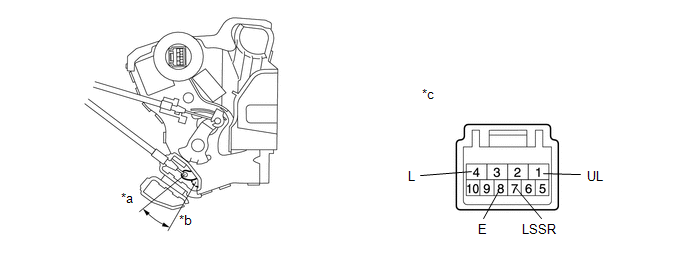
2. INSPECT FRONT DOOR LOCK ASSEMBLY RH
(a) Check the door lock motor operation.
(1) Apply battery voltage to the door lock motor connector and check the operation of the door lock.
 Text in Illustration
|
*a |
Unlock |
*b |
Lock |
|
*c |
Component without harness connected (Front Door Lock Assembly RH) |
- |
- |
OK:
|
Measurement Condition |
Specified Condition |
|---|---|
|
Battery positive (+) → 4 (L) Battery negative (-) → 1 (UL) |
Lock |
|
Battery positive (+) → 1 (UL) Battery negative (-) → 4 (L) |
Unlock |
- If the result is not as specified, replace the front door lock assembly.
(b) Check the detection switch.
(1) Measure the resistance according to the value(s) in the table below.
Standard Resistance:
|
Tester Connection |
Switch Condition |
Specified Condition |
|---|---|---|
|
7 (LSSR) - 8 (E) |
Lock |
10 kΩ or higher |
|
7 (LSSR) - 8 (E) |
Unlock |
Below 1 Ω |
- If the result is not as specified, replace the front door lock assembly.
 Removal
REMOVAL
CAUTION / NOTICE / HINT
HINT:
Use the same procedure for the RH and LH sides.
The procedure listed below is for the LH side.
PROCEDURE
1. DISCONNECT CABLE FROM NEGATIVE ...
 Installation
INSTALLATION
CAUTION / NOTICE / HINT
HINT:
Use the same procedure for the RH and LH sides.
The procedure listed below is for the LH side.
PROCEDURE
1. INSTALL FRONT DOOR INSIDE ...
Other materials about Toyota 4Runner:
Disassembly
DISASSEMBLY
PROCEDURE
1. REMOVE NO. 1 HEATER TO REGISTER DUCT
(a) Remove the 4 screws and No. 1 heater to register duct.
2. REMOVE NO. 2 HEATER TO REGISTER DUCT
(a) Remove the 4 screws and No ...
Problem Symptoms Table
PROBLEM SYMPTOMS TABLE
HINT:
Use the table below to help determine the cause of problem symptoms.
If multiple suspected areas are listed, the potential causes of the symptoms
are listed in order of probability in the "Suspected Area" ...

0.0085