Toyota 4Runner: Removal
REMOVAL
CAUTION / NOTICE / HINT
HINT:
- Use the same procedure for the RH and LH sides.
- The procedure listed below is for the LH side.
PROCEDURE
1. DISCONNECT CABLE FROM NEGATIVE BATTERY TERMINAL
CAUTION:
Wait at least 90 seconds after disconnecting the cable from the negative (-) battery terminal to disable the SRS system.
NOTICE:
When disconnecting the cable, some systems need to be initialized after the cable
is reconnected (See page .gif) ).
).
2. REMOVE FRONT DOOR LOWER FRAME BRACKET GARNISH LH
3. REMOVE DOOR NO. 2 INSIDE HANDLE BEZEL LH
4. REMOVE FRONT DOOR TRIM BOARD SUB-ASSEMBLY LH
5. REMOVE FRONT DOOR INNER GLASS WEATHERSTRIP LH
6. REMOVE FRONT DOOR SERVICE HOLE COVER LH
7. REMOVE FRONT DOOR GLASS SUB-ASSEMBLY LH
8. REMOVE FRONT DOOR GLASS RUN LH
9. REMOVE FRONT DOOR REAR LOWER FRAME SUB-ASSEMBLY LH
10. REMOVE FRONT DOOR OUTSIDE HANDLE COVER LH
11. REMOVE FRONT DOOR LOCK ASSEMBLY LH
(a) Disconnect the connector.
|
(b) Using a T30 "TORX" wrench, remove the 3 screws. |
|
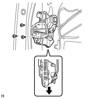
(c) Slide the front door lock assembly downward, pull out the front door lock open rod from the outside handle frame, and remove the front door lock assembly and cables as a unit.
(d) Remove the front door lock open rod from the front door lock assembly.
(e) Remove the door lock wiring harness seal from the front door lock assembly.
12. REMOVE FRONT DOOR LOCK REMOTE CONTROL CABLE ASSEMBLY LH
13. REMOVE FRONT DOOR INSIDE LOCKING CABLE ASSEMBLY LH
 Components
COMPONENTS
ILLUSTRATION
ILLUSTRATION
...
 Inspection
INSPECTION
PROCEDURE
1. INSPECT FRONT DOOR LOCK ASSEMBLY LH
(a) Check the door lock motor operation.
(1) Apply battery voltage to the motor connector and check the operation of the
door lock.
...
Other materials about Toyota 4Runner:
Transmission Fluid Temperature Sensor "A" Circuit Low Input (P0712,P0713)
DESCRIPTION
Refer to DTC P0711 (See page
).
DTC Code
DTC Detection Condition
Trouble Area
P0712
ATF temperature sensor resistance is below 79 Ω for 0.5 sec. or more
(1-trip detection logic ...
Stop Light Switch
Components
COMPONENTS
ILLUSTRATION
On-vehicle Inspection
ON-VEHICLE INSPECTION
PROCEDURE
1. INSPECT STOP LIGHT SWITCH ASSEMBLY
(a) Disconnect the connector from the stop light switch assembly.
...

0.007