Toyota 4Runner: Inspection
INSPECTION
PROCEDURE
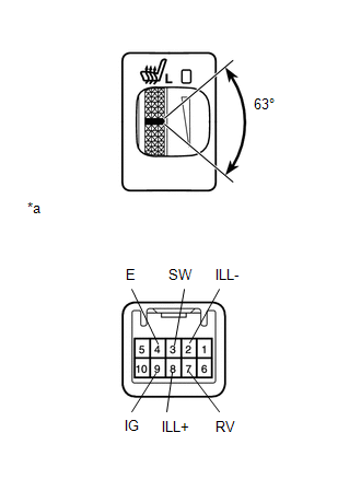
1. INSPECT SEAT HEATER SWITCH LH
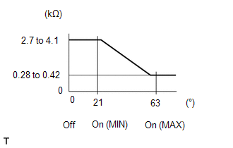
(a) Measure the resistance according to the value(s) in the table below.
Standard Resistance:
|
Tester Connection |
Switch Condition |
Specified Condition |
|---|---|---|
|
3 (SW) - 7 (RV) |
Switch off |
2.7 to 4.1 kΩ |
|
Switch on (Min.) |
||
|
Switch on (Max.) |
0.28 to 0.42 kΩ |
HINT:
As the dial is being turned, the resistance changes gradually.
If the result is not as specified, replace the seat heater switch.
Text in Illustration|
*a |
Component without harness connected (Seat Heater Switch) |
(b) Apply battery voltage to the switch connector, and check that the seat heater switch illuminates.
OK:
|
Measurement Condition |
Specified Condition |
|---|---|
|
Battery positive (+) → 8 (ILL+) Battery negative (-) → 2 (ILL-) |
Illuminates |
If the result is not as specified, replace the seat heater switch.
(c) Apply battery voltage to the switch connector, and check that the seat heater switch indicator illuminates.
OK:
|
Measurement Condition |
Switch Condition |
Specified Condition |
|---|---|---|
|
Battery positive (+) → 9 (IG) Battery negative (-) → 4 (E) |
Switch on |
Indicator illuminates |
If the result is not as specified, replace the seat heater switch.
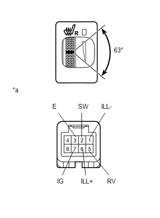
2. INSPECT SEAT HEATER SWITCH RH
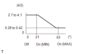
(a) Measure the resistance according to the value(s) in the table below.
Standard Resistance:
|
Tester Connection |
Switch Condition |
Specified Condition |
|---|---|---|
|
2 (SW) - 5 (RV) |
Switch off |
2.7 to 4.1 kΩ |
|
Switch on (Min.) |
||
|
Switch on (Max.) |
0.28 to 0.42 kΩ |
HINT:
As the dial is being turned, the resistance changes gradually.
If the result is not as specified, replace the seat heater switch.
Text in Illustration|
*a |
Component without harness connected (Seat Heater Switch) |
(b) Apply battery voltage to the switch connector, and check that the seat heater switch illuminates.
OK:
|
Measurement Condition |
Specified Condition |
|---|---|
|
Battery positive (+) → 6 (ILL+) Battery negative (-) → 1 (ILL-) |
Illuminates |
If the result is not as specified, replace the seat heater switch.
(c) Apply battery voltage to the switch connector, and check that the seat heater switch indicator illuminates.
OK:
|
Measurement Condition |
Switch Condition |
Specified Condition |
|---|---|---|
|
Battery positive (+) → 7 (IG) Battery negative (-) → 3 (E) |
Switch on |
Indicator illuminates |
If the result is not as specified, replace the seat heater switch.
 Components
COMPONENTS
ILLUSTRATION
...
 Removal
REMOVAL
PROCEDURE
1. REMOVE SHIFT LEVER KNOB SUB-ASSEMBLY
2. REMOVE SHIFT LEVER KNOB SUB-ASSEMBLY (for VF2A)
3. REMOVE UPPER CONSOLE PANEL SUB-ASSEMBLY
4. REMOVE SEAT HEATER SWITCH
...
Other materials about Toyota 4Runner:
Precaution
PRECAUTION
1. IGNITION SWITCH EXPRESSION
HINT:
The type of ignition switch used on this model differs according to the specifications
of the vehicle. The expressions listed in the table below are used in this section.
Expression
Ign ...
Alarm
The system sounds the alarm and flashes the lights when forced entry is
detected.
Triggering of the alarm
The alarm is triggered in the following situations when the alarm is set:
• A locked door is unlocked or opened in any way other than using the ...

0.0102