Toyota 4Runner: Removal
REMOVAL
PROCEDURE
1. REMOVE SHIFT LEVER KNOB SUB-ASSEMBLY
.gif)
2. REMOVE SHIFT LEVER KNOB SUB-ASSEMBLY (for VF2A)
3. REMOVE UPPER CONSOLE PANEL SUB-ASSEMBLY
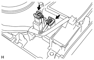
4. REMOVE SEAT HEATER SWITCH
|
(a) Disconnect the 2 connectors. |
|
|
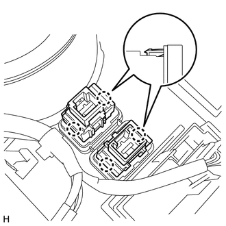
(b) Detach the 4 claws and remove the 2 switches. |
|
 Inspection
INSPECTION
PROCEDURE
1. INSPECT SEAT HEATER SWITCH LH
(a) Measure the resistance according to the value(s) in the table below.
Standard Resistance:
Tester Connection
Sw ...
 Installation
INSTALLATION
PROCEDURE
1. INSTALL SEAT HEATER SWITCH
(a) Attach the 4 claws to install the 2 switches.
(b) Connect the 2 connectors.
2. INSTALL UPPER CONSOLE PANEL SUB-ASSEMBLY
3. INSTALL SHI ...
Other materials about Toyota 4Runner:
Open or Short in Rear Speed Sensor RH Circuit (C1407,C1408)
DESCRIPTION
Refer to DTCs C1401 and C1402 (See page ).
DTC Code
DTC Detection Condition
Trouble Area
C1407
C1408
Either condition is met:
An open in the speed sensor signal circui ...
Rear Door Speaker
Components
COMPONENTS
ILLUSTRATION
Removal
REMOVAL
CAUTION / NOTICE / HINT
HINT:
Use the same procedure for the RH and LH sides.
The procedure listed below is for the LH side.
PROCEDURE
1. REMOVE REAR DOOR INSIDE HANDLE BEZEL L ...

0.0072