Toyota 4Runner: Inspection
INSPECTION
PROCEDURE
1. INSPECT HOOD LOCK ASSEMBLY (ENGINE HOOD COURTESY SWITCH)
(a) Measure the resistance according to the value(s) in the table below.
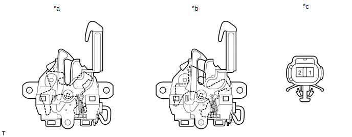
Standard Resistance:
|
Tester Connection |
Condition |
Specified Condition |
|---|---|---|
|
1 - 2 |
Unlock position |
Below 1 Ω |
|
1 - 2 |
Lock position |
10 kΩ or higher |
If the result is not as specified, replace the hood lock assembly.
Text in Illustration|
*a |
Unlock Position |
*b |
Lock Position |
|
*c |
Component without harness connected (Hood Lock Assembly (Engine Hood Courtesy Switch)) |
- |
- |
 Components
COMPONENTS
ILLUSTRATION
...
 Removal
REMOVAL
PROCEDURE
1. REMOVE FRONT BUMPER COVER (w/o Intuitive Parking Assist System)
(See page )
2. REMOVE FRONT BUMPER COVER (w/ Intuitive Parking Assist System)
(See page )
3. REMOVE HIGH PI ...
Other materials about Toyota 4Runner:
Cellular Phone Inspection
CAUTION / NOTICE / HINT
HINT:
If the operation of a cellular phone or the navigation receiver assembly is requested,
make sure to follow the instructions closely and perform the operation.
PROCEDURE
1.
CHECK USAGE CONDITION
...
Electrical Key Oscillator(for Front Floor)
Components
COMPONENTS
ILLUSTRATION
Installation
INSTALLATION
PROCEDURE
1. INSTALL INDOOR NO. 1 ELECTRICAL KEY ANTENNA ASSEMBLY
(a) Attach the clamp to install the indoor No. 1 electrical key antenna.
...

0.0087