Toyota 4Runner: Installation
INSTALLATION
PROCEDURE
1. INSTALL SPIRAL CABLE SUB-ASSEMBLY
(a) Attach the 3 claws to install the spiral cable.
CAUTION:
When replacing the spiral cable with a new one, remove the lock pin before installing the steering wheel assembly.
(b) Connect the connectors to the spiral cable.
NOTICE:
When handling the airbag connector, take care not to damage the airbag wire harness.
2. INSTALL UPPER STEERING COLUMN COVER
.gif)
3. INSTALL LOWER STEERING COLUMN COVER
4. ADJUST SPIRAL CABLE SUB-ASSEMBLY
(a) Turn the ignition switch off.
(b) Disconnect the cable from the negative (-) battery terminal.
CAUTION:
Wait at least 90 seconds after disconnecting the cable from the negative (-) battery terminal to disable the SRS system.
NOTICE:
When disconnecting the cable, some systems need to be initialized after the cable
is reconnected (See page ).
(c) Check if the spiral cable sub-assembly is centered.
- The connector is positioned at the top.
- The colored roller or flat cable can be seen in the inspection window.
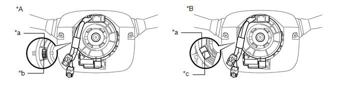 Text in Illustration
|
*A |
Colored Roller Type |
*B |
Flat Cable Type |
|
*a |
Inspection Window |
*b |
Colored Roller |
|
*c |
Flat Cable |
- |
- |
(d) If the spiral cable sub-assembly is not centered, center it.
NOTICE:
Make sure to observe the following precautions, otherwise the spiral cable sub-assembly may be damaged.
- Do not rotate the spiral cable sub-assembly with the battery connected and the ignition switch turned to ON.
- Do not rotate the spiral cable sub-assembly using the airbag wire harness.
- Do not rotate the spiral cable sub-assembly with excessive force.
(1) Rotate the spiral cable sub-assembly counterclockwise slowly by hand until it stops.
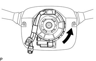 Text in Illustration
.png) |
Rotation Direction |
NOTICE:
If the spiral cable sub-assembly is rotated clockwise in this step, it may be damaged and may no longer be able to be centered. Make sure to only rotate the spiral cable sub-assembly counterclockwise.
|
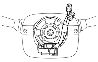
(2) If the connector is not positioned at the bottom of the rotation of the spiral cable sub-assembly when the spiral cable sub-assembly is turned until it stops, turn the spiral cable sub-assembly clockwise until the connector is positioned at the bottom as shown in the illustration. |
|
(3) Rotate the spiral cable sub-assembly clockwise approximately 2.5 times.
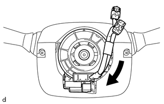 Text in Illustration
|
|
Rotation Direction |
NOTICE:
If the spiral cable sub-assembly is rotated clockwise 5 times or more from the point at which it stops and the connector is positioned at the bottom, the spiral cable sub-assembly may be damaged.
(4) Check that the spiral cable sub-assembly is centered.
- The connector is positioned at the top.
- The colored roller or flat cable can be seen in the inspection window.
Text in Illustration
|
*A |
Colored Roller Type |
*B |
Flat Cable Type |
|
*a |
Inspection Window |
*b |
Colored Roller |
|
*c |
Flat Cable |
- |
- |
NOTICE:
If the spiral cable sub-assembly cannot be centered, it may be damaged. Replace the spiral cable sub-assembly with a new one.
5. INSTALL STEERING WHEEL ASSEMBLY
(a) Install the steering wheel assembly (See page
).
 Inspection
INSPECTION
PROCEDURE
1. INSPECT SPIRAL CABLE SUB-ASSEMBLY
(a) If there are any defects as mentioned below, replace the spiral cable with
a new one:
Scratches, cracks, dents or chips in the conne ...
 Steering Pad
...
Other materials about Toyota 4Runner:
General Maintenance
GENERAL MAINTENANCE
PROCEDURE
1. INSPECT STEERING LINKAGE AND GEAR HOUSING
(a) Check the steering wheel free play.
(b) Check the steering linkage for looseness or damage.
(1) Check that the tie rod ends do not have excessive play.
(2) Check that the dust ...
Deactivating the curtain shield airbags in a vehicle rollover
On/off (hold for a few seconds)
Vehicles without a smart key system: The “RSCA OFF” indicator turns on. (only
when the engine switch is in the “ON” position).
The roll sensing function for the curtain shield airbags and seat belt
pretensioners ...

0.0265