Toyota 4Runner: Installation
INSTALLATION
CAUTION / NOTICE / HINT
CAUTION:
Wear protective gloves. Sharp areas on the parts may injure your hands.
HINT:
The procedure listed below is for the RH side.
PROCEDURE
1. INSTALL FRONT SEAT ASSEMBLY
(a) Place the front seat assembly in the cabin.
NOTICE:
Be careful not to damage the vehicle body.
(b) Connect the seat wire connectors under the seat.
(c) Temporarily install the front seat assembly with the 4 bolts.
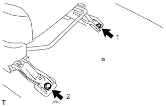
(d) Operate the seat track adjusting handle to move the front seat assembly to the rearmost position.
|
(e) Tighten the 2 bolts in the order indicated in the illustration. Torque: 37 N·m {377 kgf·cm, 27 ft·lbf} |
|
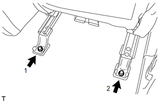
(f) Operate the seat track adjusting handle to move the front seat assembly to the foremost position.
|
(g) Tighten the 2 bolts in the order indicated in the illustration. Torque: 37 N·m {377 kgf·cm, 27 ft·lbf} |
|
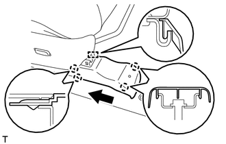
2. INSTALL OUTER SEAT TRACK COVER RH
|
(a) Move the outer seat track cover RH in the direction of the arrow to attach the 4 guides. |
|
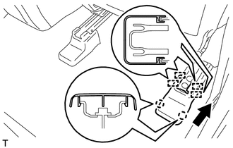
(b) Attach the 2 claws to install the outer seat track cover RH.
3. INSTALL INNER SEAT TRACK BRACKET COVER RH
|
(a) Move the inner seat track bracket cover RH in the direction of the arrow to attach the 2 guides. |
|
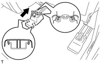
(b) Attach the 2 claws to install the inner seat track bracket cover RH.
4. INSTALL FRONT SEAT OUTER TRACK BRACKET COVER RH
(a) Operate the seat track adjusting handle to move the seat to the rearmost position.
|
(b) Move the front seat outer track bracket cover RH in the direction of the arrow to attach the 2 claws and guide. |
|
(c) Attach the 2 claws to install the front seat outer track bracket cover RH.
5. INSTALL FRONT SEAT INNER TRACK BRACKET COVER RH
|
(a) Move the front seat inner track bracket cover RH in the direction of the arrow to attach the 2 guides. |
|
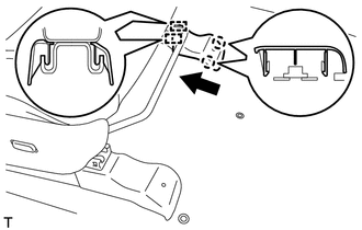
(b) Attach the 2 claws to install the front seat inner track bracket cover RH.
6. INSTALL FRONT SEAT HEADREST ASSEMBLY
(a) Install the front seat headrest assembly.
7. CONNECT CABLE TO NEGATIVE BATTERY TERMINAL
NOTICE:
When disconnecting the cable, some systems need to be initialized after the cable
is reconnected (See page .gif) ).
).
Torque:
5.4 N·m {55 kgf·cm, 48 in·lbf}
8. CHECK SRS WARNING LIGHT
(See page )
 Removal
REMOVAL
CAUTION / NOTICE / HINT
CAUTION:
Wear protective gloves. Sharp areas on the parts may injure your hands.
HINT:
The procedure listed below is for the RH side.
PROCEDURE
1. PRECAUTION
...
 Reassembly
REASSEMBLY
CAUTION / NOTICE / HINT
CAUTION:
Wear protective gloves. Sharp areas on the parts may injure your hands.
PROCEDURE
1. INSTALL FRONT SEAT SIDE AIRBAG ASSEMBLY
2. INSTALL SEPARATE TY ...
Other materials about Toyota 4Runner:
Navigation Receiver Assembly Power Source Circuit
DESCRIPTION
This is the power source circuit to operate the navigation receiver assembly.
WIRING DIAGRAM
CAUTION / NOTICE / HINT
NOTICE:
Inspect the fuses for circuits related to this system before performing the following
inspection procedure.
PROCE ...
How To Proceed With Troubleshooting
CAUTION / NOTICE / HINT
HINT:
Use these procedures to troubleshoot the sliding roof system.
*: Use the Techstream.
PROCEDURE
1.
VEHICLE BROUGHT TO WORKSHOP
NEXT
...

0.0116