Toyota 4Runner: Installation
INSTALLATION
PROCEDURE
1. INSTALL NO. 2 TELEPHONE BRACKET
(a) Install the bracket with the 2 bolts.
2. INSTALL NO. 1 TELEPHONE BRACKET
(a) Install the bracket with the 3 bolts.
(b) Connect the 2 connectors.
3. INSTALL MAYDAY BATTERY WITH BRACKET
(a) Attach the 2 claws to install the mayday battery.
(b) Install the bracket with the bolt.
Torque:
13 N·m {133 kgf·cm, 10 ft·lbf}
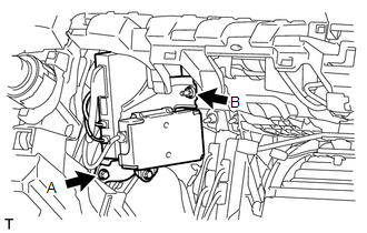
4. INSTALL DCM (TELEMATICS TRANSCEIVER)
(a) Insert the DCM (telematics transceiver) with bracket into the vehicle.
|
(b) Install the DCM (telematics transceiver) with bracket with the bolt and nut. Torque: for bolt A : 13 N·m {133 kgf·cm, 10 ft·lbf} for nut B : 12 N·m {122 kgf·cm, 9 ft·lbf} |
|
(c) Connect the connectors.
5. INSTALL LOWER INSTRUMENT PANEL SUB-ASSEMBLY
.gif)
6. INSTALL INSTRUMENT PANEL BOX DOOR COVER
7. INSTALL LOWER NO. 2 INSTRUMENT PANEL AIRBAG ASSEMBLY
8. INSTALL LOWER INSTRUMENT COVER LH
9. INSTALL NO. 2 INSTRUMENT PANEL UNDER COVER SUB-ASSEMBLY
10. INSTALL NO. 2 INSTRUMENT CLUSTER FINISH PANEL GARNISH
11. INSTALL COWL SIDE TRIM BOARD RH
12. INSTALL DOOR SCUFF PLATE ASSEMBLY RH
13. CONNECT CABLE TO NEGATIVE BATTERY TERMINAL
NOTICE:
When disconnecting the cable, some systems need to be initialized after the cable
is reconnected (See page ).
14. CHECK SRS WARNING LIGHT
(a) Check the SRS warning light (See page ).
15. PERFORM REGISTRATION
(a) Perform registration (See page ).
NOTICE:
When replacing the mayday battery or DCM (telematics transceiver) (together with the mayday battery), perform registration.
 Removal
REMOVAL
PROCEDURE
1. DISCONNECT CABLE FROM NEGATIVE BATTERY TERMINAL
CAUTION:
Wait at least 90 seconds after disconnecting the cable from the negative (-)
battery terminal to disable the SRS sys ...
 Manual(sos)switch
Components
COMPONENTS
ILLUSTRATION
ILLUSTRATION
Installation
INSTALLATION
PROCEDURE
1. INSTALL TELEPHONE SWITCH ASSEMBLY
(a) Install the telephone switch with the 2 screws.
(b) Connec ...
Other materials about Toyota 4Runner:
Security Indicator Light Circuit
DESCRIPTION
When the theft deterrent system is in the disarmed state, the security
indicator light flashes continuously when the engine immobiliser system
is set, and does not illuminate when the engine immobiliser system is not
set.
Whe ...
Precaution
PRECAUTION
1. IGNITION SWITCH EXPRESSION
HINT:
The type of ignition switch used on this model differs depending on the specifications
of the vehicle. The expressions listed in the table below are used in this section.
Expression
Ign ...

0.0084