Toyota 4Runner: Installation
INSTALLATION
CAUTION / NOTICE / HINT
PROCEDURE
1. INSTALL BRAKE MASTER CYLINDER SUB-ASSEMBLY
(a) Install a new O-ring to the brake master cylinder sub-assembly.
(b) Install the brake master cylinder sub-assembly with 2 nuts.
Torque:
13 N·m {127 kgf·cm, 9 ft·lbf}
|
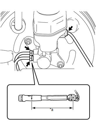
(c) Using a union nut wrench, connect the 2 brake lines to the brake master cylinder sub-assembly. Text in Illustration
Torque: Specified tightening torque : 20 N·m {199 kgf·cm, 14 ft·lbf} HINT:
|
|
(d) Attach the clamp and connect the connector.
2. BLEED BRAKE SYSTEM
.gif)
 Reassembly
REASSEMBLY
PROCEDURE
1. INSTALL MASTER CYLINDER RESERVOIR GROMMET
(a) Apply a light coat of lithium soap base glycol grease to 2 new master cylinder
reservoir grommets.
(b) Install the 2 master ...

Other materials about Toyota 4Runner:
Rear Occupant Classification Sensor RH Circuit Malfunction (B1783)
DESCRIPTION
The rear occupant classification sensor RH circuit consists of the occupant classification
ECU and rear occupant classification sensor RH.
DTC B1783 is stored when a malfunction is detected in the rear occupant classification
sensor RH circui ...
Door Courtesy Light(for Rear Door)
Components
COMPONENTS
ILLUSTRATION
Removal
REMOVAL
CAUTION / NOTICE / HINT
HINT:
Use the same procedure for the RH and LH sides.
The procedure listed below is for the LH side.
PROCEDURE
1. REMOVE REAR DOOR INSIDE HANDLE BEZEL L ...

0.0181