Toyota 4Runner: Installation
INSTALLATION
PROCEDURE
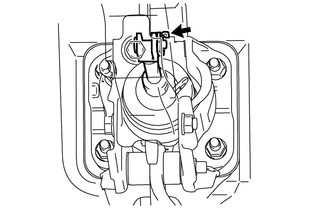
1. INSTALL BRAKE PEDAL SUPPORT ASSEMBLY
(a) Temporarily install the set bolt.
(b) Install the brake booster assembly (See page
.gif) ).
).
(c) Install the brake master cylinder sub-assembly (See page
).
(d) Install the brake pedal support assembly with the 4 nuts.
Torque:
14 N·m {145 kgf·cm, 10 ft·lbf}
(e) Install the brake pedal support reinforcement set bolt.
Torque:
20 N·m {204 kgf·cm, 15 ft·lbf}
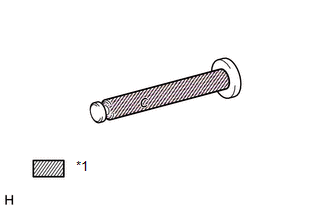
2. INSTALL PUSH ROD PIN
|
(a) Apply a light coat of lithium soap base glycol grease to the inner surface of the hole on the brake pedal lever. Text in Illustration
|
|
|
(b) Set the master cylinder push rod clevis in place, insert the push rod pin from the left side of the vehicle and then install a new clip. |
|
3. INSTALL BRAKE PEDAL RETURN SPRING
(a) Apply a light coat of lithium soap base glycol grease to the inner surface of the hole on the brake pedal support assembly.
(b) Install the brake pedal return spring to the brake pedal support assembly.
4. CONNECT BRAKE PEDAL LOAD SENSING SWITCH
(a) Connect the brake pedal load sensing switch connector.
5. INSTALL STOP LIGHT SWITCH ASSEMBLY
(a) Install the stop light switch assembly (See page
).
(b) Connect the stop light switch connector.
6. INSTALL LOWER NO. 1 INSTRUMENT PANEL AIRBAG ASSEMBLY
(a) Install the lower No. 1 instrument panel airbag assembly (See page
).
7. CONNECT CABLE TO NEGATIVE BATTERY TERMINAL
NOTICE:
When disconnecting the cable, some systems need to be initialized after the cable
is reconnected (See page ).
8. BLEED BRAKE SYSTEM
9. CHECK AND ADJUST BRAKE PEDAL
(a) Check and adjust brake pedal (See page ).
 Reassembly
REASSEMBLY
PROCEDURE
1. INSTALL STOP LIGHT SWITCH MOUNTING ADJUSTER
(a) Install a new stop light switch mounting adjuster to the brake pedal support
assembly.
2. INSTALL BRAKE PEDAL PAD
(a) Ins ...
 Brake System
...
Other materials about Toyota 4Runner:
Operating Light Control Rheostat does not Change Light Brightness
DESCRIPTION
When the light control rheostat dial is turned upward, the combination meter
and vehicle interior illumination will become brighter. When the light control rheostat
dial is turned downward, the combination meter and vehicle illumination will d ...
Lost Communication with ECM / PCM (U0100,U0129,U0142,U0155)
DESCRIPTION
The power management control ECU receives information from 2 sources. It receives
information via a direct line and via the CAN communication line. If the information
from these 2 sources is inconsistent, this DTC is stored.
HINT:
When the p ...

0.0127