Toyota 4Runner: Lost Communication with Gateway Module (U1002)
DESCRIPTION
- The main body ECU (multiplex network body ECU) stores this DTC when no signals can be received from the ECUs that are memorized as those connected to the CAN MS bus.
- When the main body ECU (multiplex network body ECU) receives a response signal from the ECUs connected to the CAN MS bus, the main body ECU (multiplex network body ECU) recognizes and memorizes that the ECU is connected to the CAN MS bus. Based on this memorized data, the main body ECU (multiplex network body ECU) monitors for malfunctions in the ECUs connected to the CAN MS bus when communicating with those ECUs. If the main body ECU (multiplex network body ECU) cannot receive response signals from the ECUs that are memorized as those connected to the CAN MS bus, the main body ECU (multiplex network body ECU) determines that a malfunction exists.
- If 2 or more DTCs are output during the DTC check, one side of the CAN branch wire may be open (one side of the CANH [branch wire]/CANL [branch wire] of the ECU and/or sensor is open).
|
DTC Code |
DTC Detection Condition |
Trouble Area |
|---|---|---|
|
U1002 |
Lost communication with the gateway module. |
|
HINT:
- For vehicles with seat position memory only.
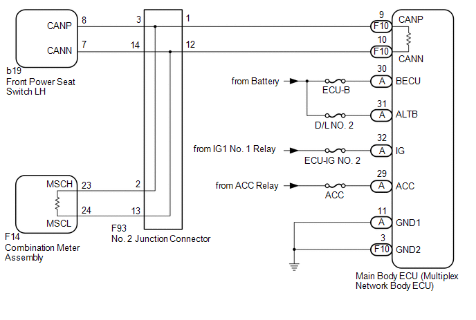
WIRING DIAGRAM
CAUTION / NOTICE / HINT
NOTICE:
Inspect the fuses for circuits related to this system before performing the following inspection procedure.
HINT:
Operating the ignition switch, any switches or any doors triggers related ECU and sensor communication with the CAN, which causes resistance variation.
PROCEDURE
|
1. |
DISCONNECT CABLE FROM NEGATIVE BATTERY TERMINAL |
(a) Disconnect the cable from the negative (-) battery terminal before measuring the resistances of the main wire and the branch wire.
CAUTION:
Wait at least 90 seconds after disconnecting the cable from the negative (-) battery terminal to disable the SRS system.
NOTICE:
- When disconnecting the cable, some systems need to be initialized after
the cable is reconnected (See page
.gif) ).
).
|
.gif)
|
2. |
CHECK FOR CAN BUS WIRE (MAIN WIRE FOR DISCONNECTION, BUS LINE FOR SHORT CIRCUIT) |
|
(a) Measure the resistance according to the value(s) in the table below. Standard Resistance:
|
|
| B | .gif) |
GO TO STEP 9 |
| C | |
GO TO STEP 18 |
|
|
3. |
CHECK FOR OPEN IN CAN BUS MAIN WIRE (NO. 2 JUNCTION CONNECTOR - COMBINATION METER ASSEMBLY) |
|
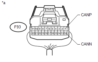
(a) Disconnect the F93 No. 2 junction connector connector. |
|
(b) Measure the resistance according to the value(s) in the table below.
Standard Resistance:
|
Tester Connection |
Switch Condition |
Specified Condition |
|---|---|---|
|
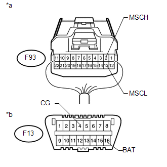
F93-2 (MSCH) - F93-13 (MSCL) |
Ignition switch off |
108 to 132 Ω |
|
*a |
Rear view of wire harness connector (to No. 2 Junction Connector) |
| NG | |
GO TO STEP 5 |
|
|
4. |
CHECK FOR OPEN IN CAN BUS MAIN WIRE (NO. 2 JUNCTION CONNECTOR - MAIN BODY ECU (MULTIPLEX NETWORK BODY ECU)) |
|
(a) Measure the resistance according to the value(s) in the table below. Standard Resistance:
|
|
| OK | |
REPAIR OR REPLACE NO. 2 JUNCTION CONNECTOR |
| NG | |
GO TO STEP 7 |
|
5. |
CONNECT CONNECTOR |
(a) Reconnect the F93 No. 2 junction connector connector.
|
|
6. |
CHECK FOR OPEN IN CAN BUS MAIN WIRE (COMBINATION METER ASSEMBLY - NO. 2 JUNCTION CONNECTOR) |
|
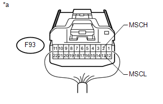
(a) Disconnect the F14 combination meter assembly connector. |
|
(b) Measure the resistance according to the value(s) in the table below.
Standard Resistance:
|
Tester Connection |
Switch Condition |
Specified Condition |
|---|---|---|
|
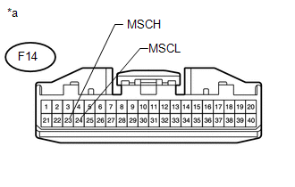
F14-23 (MSCH) - F14-24 (MSCL) |
Ignition switch off |
108 to 132 Ω |
|
*a |
Front view of wire harness connector (to Combination Meter Assembly) |
| OK | |
REPLACE COMBINATION METER ASSEMBLY |
| NG | |
REPAIR OR REPLACE CAN MAIN WIRE CONNECTED TO (COMBINATION METER ASSEMBLY - NO. 2 JUNCTION CONNECTOR) |
|
7. |
CONNECT CONNECTOR |
(a) Reconnect the F93 No. 2 junction connector connector.
|
|
8. |
CHECK FOR OPEN IN CAN BUS MAIN WIRE (MAIN BODY ECU (MULTIPLEX NETWORK BODY ECU) - NO. 2 JUNCTION CONNECTOR) |
|
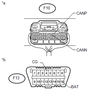
(a) Disconnect the F10 main body ECU (multiplex network body ECU) connector. |
|
.png)
(b) Measure the resistance according to the value(s) in the table below.
Standard Resistance:
|
Tester Connection |
Switch Condition |
Specified Condition |
|---|---|---|
|
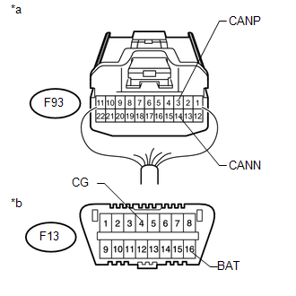
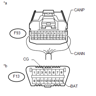
F10-9 (CANP) - F10-10 (CANN) |
Ignition switch off |
108 to 132 Ω |
|
*a |
Rear view of wire harness connector (to Main Body ECU (Multiplex Network Body ECU)) |
| OK | |
REPLACE MAIN BODY ECU (MULTIPLEX NETWORK BODY ECU) |
| NG | |
REPAIR OR REPLACE CAN MAIN WIRE CONNECTED TO (MAIN BODY ECU (MULTIPLEX NETWORK BODY ECU) - NO. 2 JUNCTION CONNECTOR) |
|
9. |
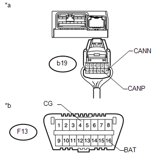
CHECK FOR SHORT IN CAN BUS WIRES (NO. 2 JUNCTION CONNECTOR - FRONT POWER SEAT SWITCH LH) |
|
(a) Disconnect the F93 No. 2 junction connector connector. |
|
(b) Measure the resistance according to the value(s) in the table below.
Standard Resistance:
|
Tester Connection |
Switch Condition |
Specified Condition |
|---|---|---|
|
F93-3 (CANP) - F93-14 (CANN) |
Ignition switch off |
200 Ω or higher |
|
F93-3 (CANP) - F13-4 (CG) |
Ignition switch off |
200 Ω or higher |
|
F93-14 (CANN) - F13-4 (CG) |
Ignition switch off |
200 Ω or higher |
|
F93-3 (CANP) - F13-16 (BAT) |
Ignition switch off |
6 kΩ or higher |
|
F93-14 (CANN) - F13-16 (BAT) |
Ignition switch off |
6 kΩ or higher |
|
*a |
Rear view of wire harness connector (to No. 2 Junction Connector) |
|
*b |
Front view of DLC3 |
| NG | |
GO TO STEP 12 |
|
|
10. |
CHECK FOR SHORT IN CAN BUS WIRES (NO. 2 JUNCTION CONNECTOR - COMBINATION METER ASSEMBLY) |
|
(a) Measure the resistance according to the value(s) in the table below. Standard Resistance:
|
|
| NG | |
GO TO STEP 14 |
|
|
11. |
CHECK FOR SHORT IN CAN BUS WIRES (NO. 2 JUNCTION CONNECTOR - MAIN BODY ECU (MULTIPLEX NETWORK BODY ECU)) |
|
(a) Measure the resistance according to the value(s) in the table below. Standard Resistance:
|
|
| OK | |
REPAIR OR REPLACE NO. 2 JUNCTION CONNECTOR |
| NG | |
GO TO STEP 16 |
|
12. |
CONNECT CONNECTOR |
(a) Reconnect the F93 No. 2 junction connector connector.
|
|
13. |
CHECK FOR SHORT IN CAN BUS WIRES (FRONT POWER SEAT SWITCH LH) |
|
(a) Disconnect the b19 front power seat switch LH connector. |
|
(b) Measure the resistance according to the value(s) in the table below.
Standard Resistance:
|
Tester Connection |
Switch Condition |
Specified Condition |
|---|---|---|
|
b19-8 (CANP) - b19-7 (CANN) |
Ignition switch off |
54 to 69 Ω |
|
b19-8 (CANP) - F13-4 (CG) |
Ignition switch off |
200 Ω or higher |
|
b19-7 (CANN) - F13-4 (CG) |
Ignition switch off |
200 Ω or higher |
|
b19-8 (CANP) - F13-16 (BAT) |
Ignition switch off |
6 kΩ or higher |
|
b19-7 (CANN) - F13-16 (BAT) |
Ignition switch off |
6 kΩ or higher |
|
*a |
Rear view of wire harness connector (to Front Power Seat Switch LH) |
|
*b |
Front view of DLC3 |
| OK | |
REPLACE FRONT POWER SEAT SWITCH LH |
| NG | |
REPAIR OR REPLACE FRONT POWER SEAT SWITCH LH CAN BRANCH WIRE OR CONNECTOR (CANP, CANN) |
|
14. |
CONNECT CONNECTOR |
(a) Reconnect the F93 No. 2 junction connector connector.
|
|
15. |
CHECK FOR SHORT IN CAN BUS WIRES (COMBINATION METER ASSEMBLY) |
|
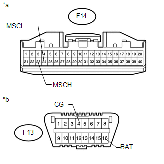
(a) Disconnect the F14 combination meter assembly connector. |
|
(b) Measure the resistance according to the value(s) in the table below.
Standard Resistance:
|
Tester Connection |
Switch Condition |
Specified Condition |
|---|---|---|
|
F14-23 (MSCH) - F14-24 (MSCL) |
Ignition switch off |
108 to 132 Ω |
|
F14-23 (MSCH) - F13-4 (CG) |
Ignition switch off |
200 Ω or higher |
|
F14-24 (MSCL) - F13-4 (CG) |
Ignition switch off |
200 Ω or higher |
|
F14-23 (MSCH) - F13-16 (BAT) |
Ignition switch off |
6 kΩ or higher |
|
F14-24 (MSCL) - F13-16 (BAT) |
Ignition switch off |
6 kΩ or higher |
|
*a |
Front view of wire harness connector (to Combination Meter Assembly) |
|
*b |
Front view of DLC3 |
| OK | |
REPLACE COMBINATION METER ASSEMBLY |
| NG | |
REPAIR OR REPLACE COMBINATION METER ASSEMBLY CAN MAIN WIRE OR CONNECTOR (MSCH, MSCL) |
|
16. |
CONNECT CONNECTOR |
(a) Reconnect the F93 No. 2 junction connector connector.
|
|
17. |
CHECK FOR SHORT IN CAN BUS WIRES (MAIN BODY ECU (MULTIPLEX NETWORK BODY ECU)) |
|
(a) Disconnect the F10 main body ECU (multiplex network body ECU) connector. |
|
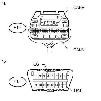
(b) Measure the resistance according to the value(s) in the table below.
Standard Resistance:
|
Tester Connection |
Switch Condition |
Specified Condition |
|---|---|---|
|
F10-9 (CANP) - F10-10 (CANN) |
Ignition switch off |
108 to 132 Ω |
|
F10-9 (CANP) - F13-4 (CG) |
Ignition switch off |
200 Ω or higher |
|
F10-10 (CANN) - F13-4 (CG) |
Ignition switch off |
200 Ω or higher |
|
F10-9 (CANP) - F13-16 (BAT) |
Ignition switch off |
6 kΩ or higher |
|
F10-10 (CANN) - F13-16 (BAT) |
Ignition switch off |
6 kΩ or higher |
|
*a |
Rear view of wire harness connector (to Main Body ECU (Multiplex Network Body ECU)) |
|
*b |
Front view of DLC3 |
| OK | |
REPLACE MAIN BODY ECU (MULTIPLEX NETWORK BODY ECU) |
| NG | |
REPAIR OR REPLACE MAIN BODY ECU (MULTIPLEX NETWORK BODY ECU) MAIN WIRE OR CONNECTOR (CANP, CANN) |
|
18. |
CHECK HARNESS AND CONNECTOR (MAIN BODY ECU (MULTIPLEX NETWORK BODY ECU) - BATTERY AND GROUND) |
(a) Remove the main body ECU (multiplex network body ECU) (See page
).
(b) Reconnect the driver side junction block assembly connectors.
(c) Connect the cable to the negative (-) battery terminal.
NOTICE:
When disconnecting the cable, some systems need to be initialized after the cable
is reconnected (See page ).
 Text in Illustration
|
*a |
Rear view of wire harness connector (to Main Body ECU (Multiplex Network Body ECU)) |
*b |
Front view of wire harness connector (to Main Body ECU (Multiplex Network Body ECU)) |
(d) Measure the resistance according to the value(s) in the table below.
Standard Resistance:
|
Tester Connection |
Condition |
Specified Condition |
|---|---|---|
|
F10-3 (GND2) - Body ground |
Always |
Below 1 Ω |
|
A-11 (GND1) - Body ground |
Always |
Below 1 Ω |
(e) Measure the voltage according to the value(s) in the table below.
Standard Voltage:
|
Tester Connection |
Condition |
Specified Condition |
|---|---|---|
|
A-30 (BECU) - Body ground |
Always |
11 to 14 V |
|
A-31 (ALTB) - Body ground |
Always |
11 to 14 V |
|
A-29 (ACC) - Body ground |
Ignition switch ACC |
11 to 14 V |
|
A-32 (IG) - Body ground |
Ignition switch ON |
11 to 14 V |
| OK | |
REPLACE MAIN BODY ECU (MULTIPLEX NETWORK BODY ECU) |
| NG | |
REPAIR OR REPLACE HARNESS OR CONNECTOR |
 Lost Communication with Gateway Module (MS Bus) (U1002,U1114)
DESCRIPTION
The main body ECU (multiplex network body ECU) stores this DTC when
no signals can be received from the ECUs that are memorized as those connected
to the CAN MS bus.
Wh ...
 Lost Communication with ECM / PCM "A" (U0100)
DESCRIPTION
DTC Code
DTC Detection Condition
Trouble Area
U0100
There is no communication from the ECM.
Power source ...
Other materials about Toyota 4Runner:
Operating a USB memory
Connecting a USB memory enables you to enjoy music from the vehicle
speakers.
Connecting a USB memory
Pull up the lid.
Open the cover and connect a USB memory.
Turn on the power of the USB memory if it is not turned on.
Press
.
Control panel
S ...
System Diagram
SYSTEM DIAGRAM
Communication Table
Transmitter
Receiver
Signal
Line
Heater control assembly
Air conditioning amplifier assembly
Defogger switch signal
LIN
...

0.0067