Toyota 4Runner: Lost Communication with ECM / PCM "A" (U0100)
DESCRIPTION
|
DTC Code |
DTC Detection Condition |
Trouble Area |
|---|---|---|
|
U0100 |
There is no communication from the ECM. |
|
HINT:
For vehicles with a smart key system only.
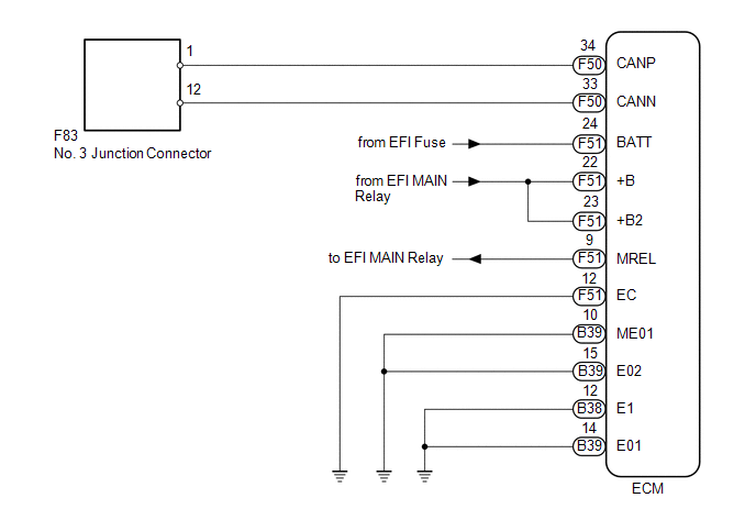
WIRING DIAGRAM
CAUTION / NOTICE / HINT
NOTICE:
Inspect the fuses for circuits related to this system before performing the following inspection procedure.
HINT:
Operating the ignition switch, any switches or any doors triggers related ECU and sensor communication with the CAN, which causes resistance variation.
PROCEDURE
|
1. |
DISCONNECT CABLE FROM NEGATIVE BATTERY TERMINAL |
(a) Disconnect the cable from the negative (-) battery terminal before measuring the resistances of the main wire and branch wire.
CAUTION:
Wait at least 90 seconds after disconnecting the cable from the negative (-) battery terminal to disable the SRS system.
NOTICE:
When disconnecting the cable, some systems need to be initialized after the cable
is reconnected (See page .gif) ).
).
|
.gif)
|
2. |
CHECK FOR OPEN IN CAN BUS MAIN WIRE (ECM MAIN WIRE) |
|
(a) Disconnect the F50 ECM connector. |
|
.png)
(b) Measure the resistance according to the value(s) in the table below.
Standard Resistance:
|
Tester Connection |
Switch Condition |
Specified Condition |
|---|---|---|
|
F50-34 (CANP) - F50-33 (CANN) |
Ignition switch off |
108 to 132 Ω |
|
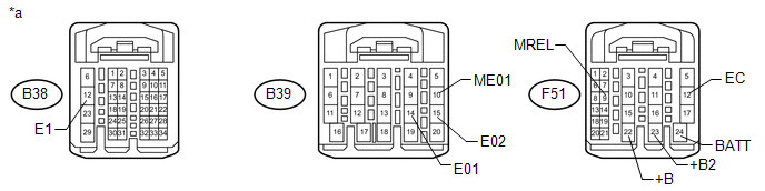
*a |
Rear view of wire harness connector (to ECM) |
| NG | .gif) |
REPAIR OR REPLACE ECM MAIN WIRE OR CONNECTOR (CANP, CANN) |
|
|
3. |
CHECK HARNESS AND CONNECTOR (ECM - BATTERY AND BODY GROUND) |
(a) Connect the cable to the negative (-) battery terminal.
NOTICE:
When disconnecting the cable, some systems need to be initialized after the cable
is reconnected (See page ).
 Text in Illustration
|
*a |
Front view of wire harness connector (to ECM) |
- |
- |
(b) Disconnect the B38, B39 and F51 ECM connectors.
(c) Measure the resistance according to the value(s) in the table below.
Standard Resistance:
|
Tester Connection |
Condition |
Specified Condition |
|---|---|---|
|
B38-12 (E1) - Body ground |
Always |
Below 1 Ω |
|
B39-14 (E01) - Body ground |
Always |
Below 1 Ω |
|
B39-15 (E02) - Body ground |
Always |
Below 1 Ω |
|
B39-10 (ME01) - Body ground |
Always |
Below 1 Ω |
|
F51-12 (EC) - Body ground |
Always |
Below 1 Ω |
(d) Measure the voltage according to the value(s) in the table below.
Standard Voltage:
|
Tester Connection |
Condition |
Specified Condition |
|---|---|---|
|
F51-24 (BATT) - Body ground |
Always |
11 to 14 V |
|
F51-23 (+B2) - Body ground |
Battery positive (+) voltage applied to terminal F51-9 (MREL) |
11 to 14 V |
|
F51-22 (+B) - Body ground |
Battery positive (+) voltage applied to terminal F51-9 (MREL) |
11 to 14 V |
| OK | |
REPLACE ECM |
| NG | |
REPAIR OR REPLACE HARNESS OR CONNECTOR |
 Lost Communication with Gateway Module (U1002)
DESCRIPTION
The main body ECU (multiplex network body ECU) stores this DTC when
no signals can be received from the ECUs that are memorized as those connected
to the CAN MS bus.
Wh ...
 Lost Communication with "Seat Control Module A" (U0208)
DESCRIPTION
DTC Code
DTC Detection Condition
Trouble Area
U0208
There is no communication from the front power seat switch LH.
...
Other materials about Toyota 4Runner:
Reassembly
REASSEMBLY
PROCEDURE
1. INSTALL REAR BUMPER SIDE BRACKET LH
(a) Attach the guide.
(b) Install the rear bumper side bracket LH with the 2 screws and clip.
2. INSTALL REAR BUMPER SIDE BRACKET RH
HINT:
Use the same procedure as for the LH side.
3. INSTALL ...
Reassembly
REASSEMBLY
PROCEDURE
1. INSTALL NO. 2 ANTENNA CORD SUB-ASSEMBLY
(a) w/o Sliding Roof:
Install the No. 2 antenna cord sub-assembly (See page
).
(b) w/ Sliding Roof:
Install the No. 2 antenna cord sub-assembly (See page
).
2. INSTALL NO. 1 ROOF WIRE
...

0.0259