Toyota 4Runner: On-vehicle Inspection
ON-VEHICLE INSPECTION
PROCEDURE
1. CHECK TURN SIGNAL FLASHER ASSEMBLY
|
(a) Measure the resistance according to the value(s) in the table below. Standard Resistance:
|
|
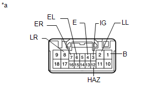
(b) Measure the voltage according to the value(s) in the table below.
Standard Voltage:
|
Tester Connection |
Condition |
Specified Condition |
|---|---|---|
|
8 (LR) - 4 (E) |
Hazard warning switch off |
Below 1 V |
|
Hazard warning switch on |
Alternating between 11 to 14 V and below 1 V (60 to 120 times per minute) |
|
|
2 (LL) - 4 (E) |
Hazard warning switch off |
Below 1 V |
|
Hazard warning switch on |
Alternating between 11 to 14 V and below 1 V (60 to 120 times per minute) |
|
|
1 (B) - 4 (E) |
Always |
11 to 14 V |
|
3 (IG) - 4 (E) |
Ignition switch ON |
11 to 14 V |
|
6 (EL) - 4 (E) |
Ignition switch ON Headlight dimmer switch (turn left) off |
9 V or higher |
|
Ignition switch ON Headlight dimmer switch (turn left) on |
Below 1 V |
|
|
7 (ER) - 4 (E) |
Ignition switch ON Headlight dimmer switch (turn right) off |
9 V or higher |
|
Ignition switch ON Headlight dimmer switch (turn right) on |
Below 1 V |
|
|
12 (HAZ) - 4 (E) |
Hazard warning switch off |
9 V or higher |
|
Hazard warning switch on |
Below 1 V |
If the result is not as specified, there may be a malfunction in the turn signal flasher assembly.
Text in Illustration|
*a |
Component with harness connected (Stop Light Switch Assembly) |
 Components
COMPONENTS
ILLUSTRATION
...
 Removal
REMOVAL
PROCEDURE
1. REMOVE DOOR SCUFF PLATE ASSEMBLY LH
2. REMOVE COWL SIDE TRIM BOARD LH
3. REMOVE NO. 2 SWITCH HOLE BASE
4. REMOVE NO. 1 INSTRUMENT CLUSTER FINISH PANEL GARNISH
5. ...
Other materials about Toyota 4Runner:
Diagnostic Trouble Code Chart
DIAGNOSTIC TROUBLE CODE CHART
NOTICE:
Turn the ignition switch off before removing parts.
HINT:
If no abnormality is found when inspecting parts, inspect the stabilizer
control ECU and ground points for poor contact.
If a trouble code is ou ...
Speed Signal Malfunction (B15C2)
DESCRIPTION
The navigation receiver assembly receives a vehicle speed signal from the combination
meter assembly and information from the navigation antenna assembly, and then adjusts
the vehicle position.
The navigation receiver assembly stores this DTC ...

0.0072