Toyota 4Runner: Meter Illumination does not Dim at Night
DESCRIPTION
If the dimmer switch is turned to TAIL, HEAD or AUTO, the main body ECU sends a TAIL relay signal, panel light illumination signal, panel relay signal and TAIL cancel OFF signal to the combination meter. Then the meter and accessory meter become dim.
HINT:
w/ TAIL Cancel Switch:
When the headlights are illuminated and the TAIL cancel switch is turned on, the meter does not dim.
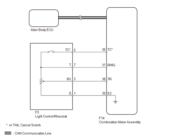
WIRING DIAGRAM
PROCEDURE
|
1. |
CHECK CAN COMMUNICATION SYSTEM |
(a) Check for DTCs (See page .gif) ).
).
Result
|
Result |
Proceed to |
|---|---|
|
CAN communication system DTC is not output |
A |
|
CAN communication system DTC is output |
B |
| B | .gif) |
Go to CAN COMMUNICATION SYSTEM |
|
.gif)
|
2. |
READ VALUE USING TECHSTREAM (LIGHT CONTROL RHEOSTAT) |
(a) Operate the Techstream according to the display and select the Data List
(See page ).
Combination Meter
|
Tester Display |
Measurement Item/Range |
Normal Condition |
Diagnostic Note |
|---|---|---|---|
|
Tail Cancel SW* |
TAIL cancel switch condition/ON or OFF |
on: TAIL cancel switch on off: TAIL cancel switch off |
- |
|
Rheostat value |
Light control rheostat switch input/Min.: 0, Max.: 100 |
Light control rheostat switch is fully turned downward (0) → fully turned upward (100) |
Unit: % |
- *: w/ TAIL Cancel Switch
OK:
Light brightness can be changed within specified range by manual operation.
| OK | |
REPLACE COMBINATION METER ASSEMBLY |
|
|
3. |
INSPECT LIGHT CONTROL RHEOSTAT |
w/o TAIL Cancel Switch:
(a) Inspect the light control rheostat.
.png)
(1) Remove the light control rheostat (See page
).
(2) Measure the resistance according to the value(s) in the table below.
Standard Resistance:
|
Tester Connection |
Switch Condition |
Specified Condition |
|---|---|---|
|
7 (T) - 1 (E) |
Always |
8 to 12 kΩ |
|
3 (RV) - 1 (E) |
Light control rheostat fully turned upward → fully turned downward |
8 to 12 kΩ → Below 50 Ω |
w/ TAIL Cancel Switch:
(b) Inspect the light control rheostat.
.png)
(1) Remove the light control rheostat (See page
).
(2) Measure the resistance according to the value(s) in the table below.
Standard Resistance:
|
Tester Connection |
Switch Condition |
Specified Condition |
|---|---|---|
|
7 (T) - 5 (TC) |
TAIL cancel switch off → on |
1 MΩ or higher → Below 1 Ω |
|
7 (T) - 1 (E) |
Always |
8 to 12 kΩ |
|
3 (RV) - 1 (E) |
Light control rheostat fully turned upward → fully turned downward |
8 to 12 kΩ → Below 50 Ω |
| NG | |
REPLACE LIGHT CONTROL RHEOSTAT |
|
|
4. |
CHECK HARNESS AND CONNECTOR (COMBINATION METER - LIGHT CONTROL RHEOSTAT) |
(a) Disconnect the F14 meter connector.
(b) Disconnect the F5 rheostat connector.
(c) Measure the resistance according to the value(s) in the table below.
Standard Resistance:
|
Tester Connection |
Condition |
Specified Condition |
|---|---|---|
|
F14-37 (RHIG) - F5-7 (T) |
Always |
Below 1 Ω |
|
F14-38 (TR) - F5-3 (RV) |
||
|
F14-39 (E2) - F5-1 (E) |
||
|
F14-36 (TC) - F5-5 (TC)* |
- *: w/ TAIL Cancel Switch
| OK | |
REPLACE COMBINATION METER ASSEMBLY |
| NG | |
REPAIR OR REPLACE HARNESS OR CONNECTOR |
 Operating Light Control Rheostat does not Change Light Brightness
DESCRIPTION
When the light control rheostat dial is turned upward, the combination meter
and vehicle interior illumination will become brighter. When the light control rheostat
dial is turned dow ...
 Meter Illumination is Always Dark
DESCRIPTION
This inspection is only for vehicles with automatic light control.
The meter CPU receives signals from this circuit to adjust the illumination of
the meter, instrument panel and access ...
Other materials about Toyota 4Runner:
Removal
REMOVAL
CAUTION / NOTICE / HINT
HINT:
Use the same procedure for the RH and LH sides.
The procedure listed below is for the LH side.
PROCEDURE
1. DISCONNECT CABLE FROM NEGATIVE BATTERY TERMINAL
CAUTION:
Wait at least 90 seconds after d ...
Installation
INSTALLATION
PROCEDURE
1. INSTALL HOOD LOCK ASSEMBLY
(a) Apply MP grease to the sliding areas of the hood lock assembly.
(b) Connect the hood lock control cable assembly.
(c) Connect the connector.
(d) Install the hood lock assembly with the 3 ...

0.0158