Toyota 4Runner: Operating Light Control Rheostat does not Change Light Brightness
DESCRIPTION
When the light control rheostat dial is turned upward, the combination meter and vehicle interior illumination will become brighter. When the light control rheostat dial is turned downward, the combination meter and vehicle illumination will dim.
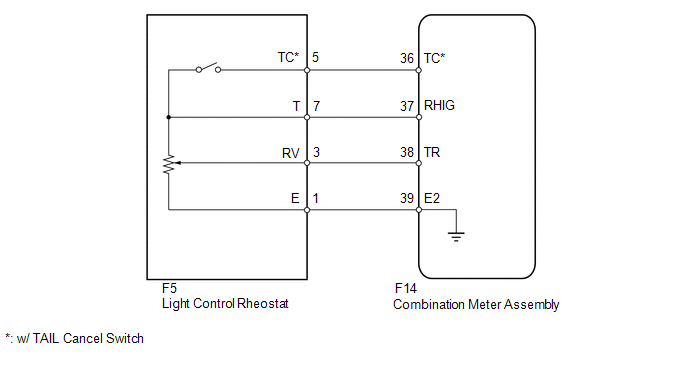
WIRING DIAGRAM
PROCEDURE
|
1. |
READ VALUE USING TECHSTREAM (LIGHT CONTROL RHEOSTAT) |
(a) Operate the Techstream according to the display and select the Data List
(See page .gif) ).
).
Combination Meter
|
Tester Display |
Measurement Item/Range |
Normal Condition |
Diagnostic Note |
|---|---|---|---|
|
Tail Cancel SW* |
TAIL cancel switch condition/ON or OFF |
ON: TAIL cancel switch on OFF: TAIL cancel switch off |
- |
|
Rheostat value |
Light control rheostat switch input/Min.: 0, Max.: 100 |
Light control rheostat switch fully turned downward (0) → fully turned upward (100) |
Unit: % |
- *: w/ TAIL Cancel Switch
OK:
Light brightness can be changed within specified range by manual operation.
| OK | .gif) |
REPLACE COMBINATION METER ASSEMBLY |
|
.gif)
|
2. |
INSPECT LIGHT CONTROL RHEOSTAT |
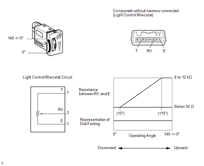
w/o TAIL Cancel Switch:
(a) Inspect the light control rheostat.
(1) Remove the light control rheostat (See page
).
(2) Measure the resistance according to the table below.
Standard Resistance:
|
Tester Connection |
Switch Condition |
Specified Condition |
|---|---|---|
|
7 (T) - 1 (E) |
Always |
8 to 12 kΩ |
|
3 (RV) - 1 (E) |
Light control rheostat fully turned upward → fully turned downward |
8 to 12 kΩ → Below 50 Ω |
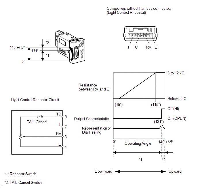
w/ TAIL Cancel Switch:
(b) Inspect the light control rheostat.
(1) Remove the light control rheostat (See page
).
(2) Measure the resistance according to the table below.
Standard Resistance:
|
Tester Connection |
Switch Condition |
Specified Condition |
|---|---|---|
|
7 (T) - 5 (TC) |
TAIL cancel switch off → on |
1 MΩ or higher → Below 1 Ω |
|
7 (T) - 1 (E) |
Always |
8 to 12 kΩ |
|
3 (RV) - 1 (E) |
Light control rheostat fully turned upward → fully turned downward |
8 to 12 kΩ → Below 50 Ω |
| NG | |
REPLACE LIGHT CONTROL RHEOSTAT |
|
|
3. |
CHECK HARNESS AND CONNECTOR (COMBINATION METER - LIGHT CONTROL RHEOSTAT) |
(a) Disconnect the F14 meter connector.
(b) Disconnect the F5 rheostat connector.
(c) Measure the resistance according to the value(s) in the table below.
Standard Resistance:
|
Tester Connection |
Condition |
Specified Condition |
|---|---|---|
|
F14-36 (TC) - F5-5 (TC)* |
Always |
Below 1 Ω |
|
F14-37 (RHIG) - F5-7 (T) |
||
|
F14-38 (TR) - F5-3 (RV) |
||
|
F14-39 (E2) - F5-1 (E) |
- *: w/ TAIL Cancel Switch
| NG | |
REPAIR OR REPLACE HARNESS OR CONNECTOR |
|
|
4. |
REPLACE COMBINATION METER ASSEMBLY |
(a) Replace the combination meter assembly with a new or normally functioning one. Perform an operation inspection.
OK:
Combination meter assembly operates normally.
| OK | |
END |
| NG | |
GO TO LIGHTING SYSTEM |
 Engine Coolant Temperature Receiver Gauge Malfunction
DESCRIPTION
In this circuit, the meter CPU receives engine coolant temperature signals from
the ECM using the CAN communication system. The meter CPU displays the engine coolant
temperature, whic ...
 Meter Illumination does not Dim at Night
DESCRIPTION
If the dimmer switch is turned to TAIL, HEAD or AUTO, the main body ECU sends
a TAIL relay signal, panel light illumination signal, panel relay signal and TAIL
cancel OFF signal to th ...
Other materials about Toyota 4Runner:
Removal
REMOVAL
PROCEDURE
1. DISCONNECT CABLE FROM NEGATIVE BATTERY TERMINAL
CAUTION:
Wait at least 90 seconds after disconnecting the cable from the negative (-)
battery terminal to disable the SRS system.
NOTICE:
When disconnecting the cable, some systems ne ...
Sending Malfunction (Navigation to APGS) (U0073,U0140)
DESCRIPTION
These DTCs are stored when a malfunction occurs in the CAN communication circuit.
DTC No.
DTC Detection Condition
Trouble Area
U0073
CAN reception error
CAN communication sys ...

0.0264