Toyota 4Runner: On-vehicle Inspection
ON-VEHICLE INSPECTION
PROCEDURE
1. REMOVE FRONT WHEEL
2. DISCONNECT FRONT DISC BRAKE CYLINDER ASSEMBLY LH
.gif)
3. REMOVE FRONT DISC
4. REMOVE FRONT AXLE HUB GREASE CAP
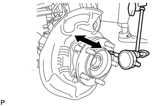
5. INSPECT FRONT AXLE HUB BEARING LOOSENESS
|
(a) Using a dial indicator, measure the looseness near the center of the axle hub. Maximum looseness: 0.05 mm (0.00197 in.) NOTICE: Make sure that the dial indicator is set at a right angle to the measurement surface. If the looseness is more than the maximum, replace the axle hub. |
|
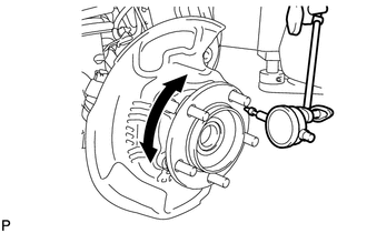
6. INSPECT FRONT AXLE HUB RUNOUT
|
(a) Using a dial indicator, measure the runout on the surface of the axle hub outside the hub bolts. Maximum runout: 0.08 mm (0.00315 in.) NOTICE: Make sure that the dial indicator is set at a right angle to the measurement surface. If the runout is more than the maximum, replace the axle hub. |
|
7. INSTALL FRONT AXLE HUB GREASE CAP
8. INSTALL FRONT DISC
9. INSTALL DISC BRAKE CYLINDER ASSEMBLY LH
10. INSTALL FRONT WHEEL
Torque:
for aluminum wheel :
103 N·m {1050 kgf·cm, 76 ft·lbf}
for steel wheel :
112 N·m {1142 kgf·cm, 83 ft·lbf}
 Components
COMPONENTS
ILLUSTRATION
...
 Removal
REMOVAL
CAUTION / NOTICE / HINT
HINT:
Use the same procedure for the RH and LH sides.
The procedure listed below is for the LH side.
PROCEDURE
1. REMOVE FRONT WHEEL
2. REMOVE D ...
Other materials about Toyota 4Runner:
Power outlets (120 V AC)
The power outlet can be used for electrical appliances.
Main switch
To use the power outlet, turn on the main switch.
The power supply starts a few seconds after the main switch is pressed.
Power outlet socket (in the console box)
Power outlet socket ...
Customization
Customizable features
Your vehicle includes a variety of electronic features that can be
personalized to suit your preferences. Programming these preferences requires
specialized equipment and may be performed by your Toyota dealer.
Some function setting ...

0.025