Toyota 4Runner: Removal
REMOVAL
CAUTION / NOTICE / HINT
HINT:
- Use the same procedure for the RH and LH sides.
- The procedure listed below is for the LH side.
PROCEDURE
1. REMOVE FRONT WHEEL
2. REMOVE DISC BRAKE CYLINDER ASSEMBLY LH
.gif)
3. REMOVE FRONT DISC
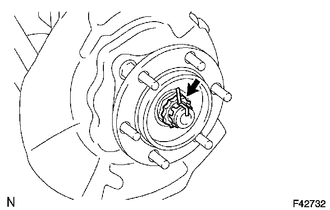
4. REMOVE FRONT AXLE HUB GREASE CAP
(a) Using a screwdriver and hammer, remove the front axle hub grease cap.
NOTICE:
Do not damage the axle hub.
5. REMOVE FRONT AXLE SHAFT NUT
|
(a) Remove the cotter pin and lock cap. |
|
(b) Remove the front axle shaft nut.
6. REMOVE FRONT AXLE HUB SUB-ASSEMBLY LH
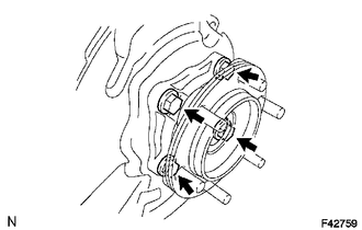
(a) Remove the 4 bolts.
(b) Using a plastic-faced hammer, tap out the front drive shaft from the front axle hub.
NOTICE:
Be careful not to damage the drive shaft boot.
(c) Remove the front axle hub and front disc dust cover.
(d) Remove the O-ring.
 On-vehicle Inspection
ON-VEHICLE INSPECTION
PROCEDURE
1. REMOVE FRONT WHEEL
2. DISCONNECT FRONT DISC BRAKE CYLINDER ASSEMBLY LH
3. REMOVE FRONT DISC
4. REMOVE FRONT AXLE HUB GREASE CAP
5. INSPECT FRONT AXLE ...
 Disassembly
DISASSEMBLY
PROCEDURE
1. REMOVE FRONT AXLE WITH ABS ROTOR BEARING ASSEMBLY LH
(a) Gently fix the front axle hub in a vise between aluminum plates.
...
Other materials about Toyota 4Runner:
Precaution
PRECAUTION
1. IGNITION SWITCH EXPRESSION
HINT:
The type of ignition switch used on this model differs according to the specifications
of the vehicle. The expressions listed in the table below are used in this section.
Expression
Ign ...
Speaker Output Short (B15C3)
DESCRIPTION
This DTC is stored when a malfunction occurs in the speakers.
DTC No.
DTC Detection Condition
Trouble Area
B15C3
A short is detected in the speaker output circuit.
...

0.0069