Toyota 4Runner: Open in One Side of CAN Branch Line
DESCRIPTION
If 2 or more ECUs and/or sensors do not appear on the Techstream "CAN Bus Check" screen, one side of the CAN branch wire may be open (one side of the CANH [branch wire]/CANL [branch wire] of the ECU and/or sensor is open).
|
Symptom |
Trouble Area |
|---|---|
|
2 or more ECUs and/or sensors do not appear on the Techstream "CAN Bus Check" screen. |
|
- *1: for 4WD
- *2: for Navigation Receiver Type
- *3: for Radio and Display Receiver Type
- *4: w/ Smart Key System
- *5: for 2WD
- *6: w/ Kinetic Dynamic Suspension System
- *7: w/o Smart Key System
WIRING DIAGRAM
.png)
.png)
.png)
.png)
CAUTION / NOTICE / HINT
HINT:
- Perform the following inspection for the ECUs (sensors) which are not displayed on the Techstream. If a malfunction cannot be identified, perform the following inspections for the ECUs (sensors) connected to the CAN communication system.
- Do not remove the combination meter assembly and ECM, as they are the end parts of the circuit. If removed, CAN communication is not possible.
- The open circuit confirmation of the combination meter assembly, ECM and main wire is performed in the Check CAN Bus Line procedure of "How to Proceed with Troubleshooting". This inspection only has procedures for checking for an open circuit on one side of the CAN branch wire.
PROCEDURE
|
1. |
CHECK FOR OPEN IN ONE SIDE OF CAN BRANCH WIRE (SKID CONTROL ECU (BRAKE ACTUATOR ASSEMBLY)) |
HINT:
For 4WD vehicles, go to "Check for Open in One Side of CAN Branch Wire (Skid Control ECU (Master Cylinder Solenoid))".
(a) Disconnect the A53 skid control ECU (brake actuator assembly) connector.
(b) Select "CAN Bus Check" on the Techstream (See page
.gif) ).
).
Result
|
Result |
Proceed to |
|---|---|
|
"Skid Control (ABS/VSC/TRAC)" not displayed on the Techstream |
A |
|
Several ECUs and sensors in addition to "Skid Control (ABS/VSC/TRAC)" not displayed on the Techstream |
B |
| B | .gif) |
GO TO STEP 3 |
|
.gif)
|
2. |
CHECK FOR OPEN IN ONE SIDE OF CAN BRANCH WIRE (SKID CONTROL ECU (BRAKE ACTUATOR ASSEMBLY) BRANCH WIRE) |
|
(a) Disconnect the cable from the negative (-) battery terminal before measuring the resistances of the main wire and branch wire. CAUTION: Wait at least 90 seconds after disconnecting the cable from the negative (-) battery terminal to disable the SRS system. NOTICE: When disconnecting the cable, some systems need to be initialized after
the cable is reconnected (See page |
|
.png)
(b) Measure the resistance according to the value(s) in the table below.
Standard Resistance:
|
Tester Connection |
Switch Condition |
Specified Condition |
|---|---|---|
|
A53-25 (CANH) - A53-14 (CANL) |
Ignition switch off |
54 to 69 Ω |
|
*a |
Front view of wire harness connector (to Skid Control ECU (Brake Actuator Assembly)) |
| OK | |
REPLACE SKID CONTROL ECU (BRAKE ACTUATOR ASSEMBLY) |
| NG | |
REPAIR OR REPLACE CAN BRANCH WIRE OR CONNECTOR (SKID CONTROL ECU (BRAKE ACTUATOR ASSEMBLY)) |
|
3. |
CHECK FOR OPEN IN ONE SIDE OF CAN BRANCH WIRE (SKID CONTROL ECU (MASTER CYLINDER SOLENOID)) |
HINT:
For 2WD vehicles, go to "Check for Open in One Side of CAN Branch Wire (Stabilizer Control ECU)".
(a) Disconnect the A6 skid control ECU (master cylinder solenoid) connector.
(b) Select "CAN Bus Check" on the Techstream (See page
).
Result
|
Result |
Proceed to |
|---|---|
|
"Skid Control (ABS/VSC/TRAC)" not displayed on the Techstream |
A |
|
Several ECUs and sensors in addition to "Skid Control (ABS/VSC/TRAC)" not displayed on the Techstream |
B |
| B | |
GO TO STEP 5 |
|
|
4. |
CHECK FOR OPEN IN ONE SIDE OF CAN BRANCH WIRE (SKID CONTROL ECU (MASTER CYLINDER SOLENOID) BRANCH WIRE) |
|
(a) Disconnect the cable from the negative (-) battery terminal before measuring the resistances of the main wire and branch wire. CAUTION: Wait at least 90 seconds after disconnecting the cable from the negative (-) battery terminal to disable the SRS system. NOTICE: When disconnecting the cable, some systems need to be initialized after
the cable is reconnected (See page |
|
(b) Measure the resistance according to the value(s) in the table below.
Standard Resistance:
|
Tester Connection |
Switch Condition |
Specified Condition |
|---|---|---|
|
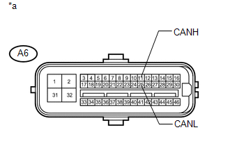
A6-11 (CANH) - A6-25 (CANL) |
Ignition switch off |
54 to 69 Ω |
|
*a |
Front view of wire harness connector (to Skid Control ECU (Master Cylinder Solenoid)) |
| OK | |
REPLACE SKID CONTROL ECU (MASTER CYLINDER SOLENOID) |
| NG | |
REPAIR OR REPLACE CAN BRANCH WIRE OR CONNECTOR (SKID CONTROL ECU (MASTER CYLINDER SOLENOID)) |
|
5. |
CHECK FOR OPEN IN ONE SIDE OF CAN BRANCH WIRE (STABILIZER CONTROL ECU) |
HINT:
For vehicles without a kinetic dynamic suspension system, go to "Check for Open in One Side of CAN Branch Wire (Main Body ECU (Multiplex Network Body ECU))".
(a) Disconnect the F70 stabilizer control ECU connector.
(b) Select "CAN Bus Check" on the Techstream (See page
).
Result
|
Result |
Proceed to |
|---|---|
|
"KDSS" not displayed on the Techstream |
A |
|
Several ECUs and sensors in addition to "KDSS" not displayed on the Techstream |
B |
| B | |
GO TO STEP 7 |
|
|
6. |
CHECK FOR OPEN IN ONE SIDE OF CAN BRANCH WIRE (STABILIZER CONTROL ECU BRANCH WIRE) |
|
(a) Disconnect the cable from the negative (-) battery terminal before measuring the resistances of the main wire and branch wire. CAUTION: Wait at least 90 seconds after disconnecting the cable from the negative (-) battery terminal to disable the SRS system. NOTICE: When disconnecting the cable, some systems need to be initialized after
the cable is reconnected (See page |
|
.png)
(b) Measure the resistance according to the value(s) in the table below.
Standard Resistance:
|
Tester Connection |
Switch Condition |
Specified Condition |
|---|---|---|
|
F70-29 (CANH) - F70-28 (CANL) |
Ignition switch off |
54 to 69 Ω |
|
*a |
Rear view of wire harness connector (to Stabilizer Control ECU) |
| OK | |
REPLACE STABILIZER CONTROL ECU |
| NG | |
REPAIR OR REPLACE CAN BRANCH WIRE OR CONNECTOR (STABILIZER CONTROL ECU) |
|
7. |
CHECK FOR OPEN IN ONE SIDE OF CAN BRANCH WIRE (MAIN BODY ECU (MULTIPLEX NETWORK BODY ECU)) |
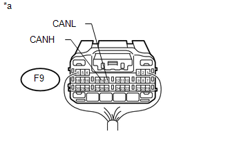
(a) Disconnect the F9 main body ECU (multiplex network body ECU) connector.
(b) Select "CAN Bus Check" on the Techstream (See page
).
Result
|
Result |
Proceed to |
|---|---|
|
"Main Body" not displayed on the Techstream |
A |
|
Several ECUs and sensors in addition to "Main Body" not displayed on the Techstream |
B |
| B | |
GO TO STEP 9 |
|
|
8. |
CHECK FOR OPEN IN ONE SIDE OF CAN BRANCH WIRE (MAIN BODY ECU (MULTIPLEX NETWORK BODY ECU) BRANCH WIRE) |
|
(a) Disconnect the cable from the negative (-) battery terminal before measuring the resistances of the main wire and branch wire. CAUTION: Wait at least 90 seconds after disconnecting the cable from the negative (-) battery terminal to disable the SRS system. NOTICE: When disconnecting the cable, some systems need to be initialized after
the cable is reconnected (See page |
|
(b) Measure the resistance according to the value(s) in the table below.
Standard Resistance:
|
Tester Connection |
Switch Condition |
Specified Condition |
|---|---|---|
|
F9-14 (CANH) - F9-13 (CANL) |
Ignition switch off |
54 to 69 Ω |
|
*a |
Rear view of wire harness connector (to Main Body ECU (Multiplex Network Body ECU)) |
| OK | |
REPLACE MAIN BODY ECU (MULTIPLEX NETWORK BODY ECU) |
| NG | |
REPAIR OR REPLACE CAN BRANCH WIRE OR CONNECTOR (MAIN BODY ECU (MULTIPLEX NETWORK BODY ECU)) |
|
9. |
CHECK FOR OPEN IN ONE SIDE OF CAN BRANCH WIRE (AIRBAG SENSOR ASSEMBLY) |
(a) Disconnect the F33 airbag sensor assembly connector.
(b) Select "CAN Bus Check" on the Techstream (See page
).
Result
|
Result |
Proceed to |
|---|---|
|
"Airbag" not displayed on the Techstream |
A |
|
Several ECUs and sensors in addition to "Airbag" not displayed on the Techstream |
B |
| B | |
GO TO STEP 11 |
|
|
10. |
CHECK FOR OPEN IN ONE SIDE OF CAN BRANCH WIRE (AIRBAG SENSOR ASSEMBLY BRANCH WIRE) |
|
(a) Disconnect the cable from the negative (-) battery terminal before measuring the resistances of the main wire and branch wire. CAUTION: Wait at least 90 seconds after disconnecting the cable from the negative (-) battery terminal to disable the SRS system. NOTICE: When disconnecting the cable, some systems need to be initialized after
the cable is reconnected (See page |
|
.png)
(b) Measure the resistance according to the value(s) in the table below.
Standard Resistance:
|
Tester Connection |
Switch Condition |
Specified Condition |
|---|---|---|
|
F33-13 (CANH) - F33-22 (CANL) |
Ignition switch off |
54 to 69 Ω |
|
*a |
Front view of wire harness connector (to Airbag Sensor Assembly) |
| OK | |
REPLACE AIRBAG SENSOR ASSEMBLY |
| NG | |
REPAIR OR REPLACE CAN BRANCH WIRE OR CONNECTOR (AIRBAG SENSOR ASSEMBLY) |
|
11. |
CHECK FOR OPEN IN ONE SIDE OF CAN BRANCH WIRE (STEERING ANGLE SENSOR (SPIRAL CABLE SUB-ASSEMBLY)) |
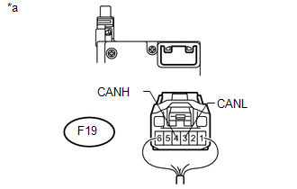
(a) Disconnect the F19 steering angle sensor (spiral cable sub-assembly) connector.
(b) Select "CAN Bus Check" on the Techstream (See page
).
Result
|
Result |
Proceed to |
|---|---|
|
"Spiral cable (Steering Angle Sensor)" not displayed on the Techstream |
A |
|
Several ECUs and sensors in addition to "Spiral cable (Steering Angle Sensor)" not displayed on the Techstream |
B |
| B | |
GO TO STEP 13 |
|
|
12. |
CHECK FOR OPEN IN ONE SIDE OF CAN BRANCH WIRE (STEERING ANGLE SENSOR (SPIRAL CABLE SUB-ASSEMBLY) BRANCH WIRE) |
|
(a) Disconnect the cable from the negative (-) battery terminal before measuring the resistances of the main wire and branch wire. CAUTION: Wait at least 90 seconds after disconnecting the cable from the negative (-) battery terminal to disable the SRS system. NOTICE: When disconnecting the cable, some systems need to be initialized after
the cable is reconnected (See page |
|
(b) Measure the resistance according to the value(s) in the table below.
Standard Resistance:
|
Tester Connection |
Switch Condition |
Specified Condition |
|---|---|---|
|
F19-4 (CANH) - F19-3 (CANL) |
Ignition switch off |
54 to 69 Ω |
|
*a |
Rear view of wire harness connector (to Steering Angle Sensor (Spiral Cable Sub-assembly)) |
| OK | |
REPLACE STEERING ANGLE SENSOR (SPIRAL CABLE SUB-ASSEMBLY) |
| NG | |
REPAIR OR REPLACE CAN BRANCH WIRE OR CONNECTOR (STEERING ANGLE SENSOR (SPIRAL CABLE SUB-ASSEMBLY)) |
|
13. |
CHECK FOR OPEN IN ONE SIDE OF CAN BRANCH WIRE (NAVIGATION RECEIVER ASSEMBLY) |
HINT:
For vehicles without a navigation receiver assembly, go to "Check for Open in One Side of CAN Branch Wire (Radio and Display Receiver Assembly)".
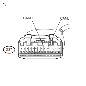
(a) Disconnect the G37 navigation receiver assembly connector.
(b) Select "CAN Bus Check" on the Techstream (See page
).
Result
|
Result |
Proceed to |
|---|---|
|
"Display and Navigation (AVN1)" not displayed on the Techstream |
A |
|
Several ECUs and sensors in addition to "Display and Navigation (AVN1)" not displayed on the Techstream |
B |
| B | |
GO TO STEP 15 |
|
|
14. |
CHECK FOR OPEN IN ONE SIDE OF CAN BRANCH WIRE (NAVIGATION RECEIVER ASSEMBLY BRANCH WIRE) |
|
(a) Disconnect the cable from the negative (-) battery terminal before measuring the resistances of the main wire and branch wire. CAUTION: Wait at least 90 seconds after disconnecting the cable from the negative (-) battery terminal to disable the SRS system. NOTICE: When disconnecting the cable, some systems need to be initialized after
the cable is reconnected (See page |
|
(b) Measure the resistance according to the value(s) in the table below.
Standard Resistance:
|
Tester Connection |
Switch Condition |
Specified Condition |
|---|---|---|
|
G37-9 (CANH) - G37-10 (CANL) |
Ignition switch off |
54 to 69 Ω |
|
*a |
Front view of wire harness connector (to Navigation Receiver Assembly) |
| OK | |
REPLACE NAVIGATION RECEIVER ASSEMBLY |
| NG | |
REPAIR OR REPLACE CAN BRACH WIRE OR CONNECTOR (NAVIGATION RECEIVER ASSEMBLY) |
|
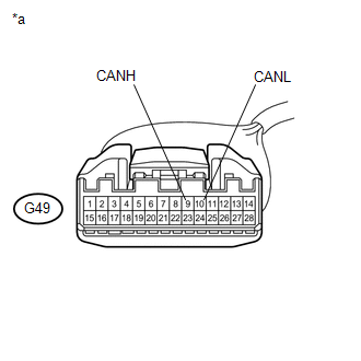
15. |
CHECK FOR OPEN IN ONE SIDE OF CAN BRANCH WIRE (RADIO AND DISPLAY RECEIVER ASSEMBLY) |
(a) Disconnect the G49 radio and display receiver assembly connector.
(b) Select "CAN Bus Check" on the Techstream (See page
).
Result
|
Result |
Proceed to |
|---|---|
|
"Display and Navigation (AVN1)" not displayed on the Techstream |
A |
|
Several ECUs and sensors in addition to "Display and Navigation (AVN1)" not displayed on the Techstream |
B |
| B | |
GO TO STEP 17 |
|
|
16. |
CHECK FOR OPEN IN ONE SIDE OF CAN BRANCH WIRE (RADIO AND DISPLAY RECEIVER ASSEMBLY BRANCH WIRE) |
|
(a) Disconnect the cable from the negative (-) battery terminal before measuring the resistances of the main wire and branch wire. CAUTION: Wait at least 90 seconds after disconnecting the cable from the negative (-) battery terminal to disable the SRS system. NOTICE: When disconnecting the cable, some systems need to be initialized after
the cable is reconnected (See page |
|
(b) Measure the resistance according to the value(s) in the table below.
Standard Resistance:
|
Tester Connection |
Switch Condition |
Specified Condition |
|---|---|---|
|
G49-9 (CANH) - G49-10 (CANL) |
Ignition switch off |
54 to 69 Ω |
|
*a |
Front view of wire harness connector (to Radio and Display Receiver Assembly) |
| OK | |
REPLACE RADIO AND DISPLAY RECEIVER ASSEMBLY |
| NG | |
REPAIR OR REPLACE CAN BRANCH WIRE CONNECTED TO RADIO AND DISPLAY RECEIVER ASSEMBLY |
|
17. |
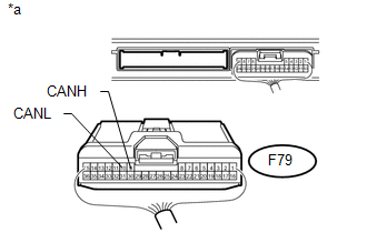
CHECK FOR OPEN IN ONE SIDE OF CAN BRANCH WIRE (CERTIFICATION ECU (SMART KEY ECU ASSEMBLY)) |
HINT:
For vehicles without a smart key system, go to "Check for Open in One Side of CAN Branch Wire (Air Conditioning Amplifier Assembly)".
(a) Disconnect the F79 certification ECU (smart key ECU assembly) connector.
(b) Select "CAN Bus Check" on the Techstream (See page
).
Result
|
Result |
Proceed to |
|---|---|
|
"Certification (Smart)" not displayed on the Techstream |
A |
|
Several ECUs and sensors in addition to "Certification (Smart)" not displayed on the Techstream |
B |
| B | |
GO TO STEP 19 |
|
|
18. |
CHECK FOR OPEN IN ONE SIDE OF CAN BRANCH WIRE (CERTIFICATION ECU (SMART KEY ECU ASSEMBLY) BRANCH WIRE) |
|
(a) Disconnect the cable from the negative (-) battery terminal before measuring the resistances of the main wire and branch wire. CAUTION: Wait at least 90 seconds after disconnecting the cable from the negative (-) battery terminal to disable the SRS system. NOTICE: When disconnecting the cable, some systems need to be initialized after
the cable is reconnected (See page |
|
(b) Measure the resistance according to the value(s) in the table below.
Standard Resistance:
|
Tester Connection |
Switch Condition |
Specified Condition |
|---|---|---|
|
F79-9 (CANH) - F79-10 (CANL) |
Ignition switch off |
54 to 69 Ω |
|
*a |
Rear view of wire harness connector (to Certification ECU (Smart Key ECU Assembly)) |
| OK | |
REPLACE CERTIFICATION ECU (SMART KEY ECU ASSEMBLY) |
| NG | |
REPAIR OR REPLACE CAN BRANCH WIRE OR CONNECTOR (CERTIFICATION ECU (SMART KEY ECU ASSEMBLY)) |
|
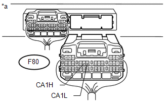
19. |
CHECK FOR OPEN IN ONE SIDE OF CAN BRANCH WIRE (POWER MANAGEMENT CONTROL ECU) |
(a) Disconnect the F80 power management control ECU connector.
(b) Select "CAN Bus Check" on the Techstream (See page
).
Result
|
Result |
Proceed to |
|---|---|
|
"Power Management1" not displayed on the Techstream |
A |
|
Several ECUs and sensors in addition to "Power Management1" not displayed on the Techstream |
B |
| B | |
GO TO STEP 21 |
|
|
20. |
CHECK FOR OPEN IN ONE SIDE OF CAN BRANCH WIRE (POWER MANAGEMENT CONTROL ECU BRANCH WIRE) |
|
(a) Disconnect the cable from the negative (-) battery terminal before measuring the resistances of the main wire and branch wire. CAUTION: Wait at least 90 seconds after disconnecting the cable from the negative (-) battery terminal to disable the SRS system. NOTICE: When disconnecting the cable, some systems need to be initialized after
the cable is reconnected (See page |
|
(b) Measure the resistance according to the value(s) in the table below.
Standard Resistance:
|
Tester Connection |
Switch Condition |
Specified Condition |
|---|---|---|
|
F80-14 (CA1H) - F80-13 (CA1L) |
Ignition switch off |
54 to 69 Ω |
|
*a |
Rear view of wire harness connector (to Power Management Control ECU) |
| OK | |
REPLACE POWER MANAGEMENT CONTROL ECU |
| NG | |
REPAIR OR REPLACE CAN BRANCH WIRE OR CONNECTOR (POWER MANAGEMENT CONTROL ECU) |
|
21. |
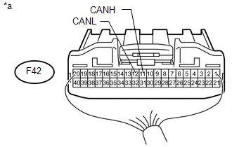
CHECK FOR OPEN IN ONE SIDE OF CAN BRANCH WIRE (AIR CONDITIONING AMPLIFIER ASSEMBLY) |
HINT:
For vehicles with a smart key system, go to "Check for Open in One Side of CAN Branch Wire (Four Wheel Drive Control ECU)".
(a) Disconnect the F42 air conditioning amplifier assembly connector.
(b) Select "CAN Bus Check" on the Techstream (See page
).
Result
|
Result |
Proceed to |
|---|---|
|
"Air Conditioning Amplifier" not displayed on the Techstream |
A |
|
Several ECUs and sensors in addition to "Air Conditioning Amplifier" not displayed on the Techstream |
B |
| B | |
GO TO STEP 23 |
|
|
22. |
CHECK FOR OPEN IN ONE SIDE OF CAN BRANCH WIRE (AIR CONDITIONING AMPLIFIER ASSEMBLY BRANCH WIRE) |
|
(a) Disconnect the cable from the negative (-) battery terminal before measuring the resistances of the main wire and branch wire. CAUTION: Wait at least 90 seconds after disconnecting the cable from the negative (-) battery terminal to disable the SRS system. NOTICE: When disconnecting the cable, some systems need to be initialized after
the cable is reconnected (See page |
|
(b) Measure the resistance according to the value(s) in the table below.
Standard Resistance:
|
Tester Connection |
Switch Condition |
Specified Condition |
|---|---|---|
|
F42-11 (CANH) - F42-12 (CANL) |
Ignition switch off |
54 to 69 Ω |
|
*a |
Rear view of wire harness connector (to Air Conditioning Amplifier Assembly) |
| OK | |
REPLACE AIR CONDITIONING AMPLIFIER ASSEMBLY |
| NG | |
REPAIR OR REPLACE CAN BRANCH WIRE OR CONNECTOR (AIR CONDITIONING AMPLIFIER ASSEMBLY) |
|
23. |
CHECK FOR OPEN IN ONE SIDE OF CAN BRANCH WIRE (FOUR WHEEL DRIVE CONTROL ECU) |
HINT:
For 2WD vehicles, go to "Check for Open in One Side of CAN Branch Wire (Yaw Rate Sensor Assembly)".
(a) Disconnect the F47 four wheel drive control ECU connector.
(b) Select "CAN Bus Check" on the Techstream (See page
).
Result
|
Result |
Proceed to |
|---|---|
|
"Four Wheel Drive Control" not displayed on the Techstream |
A |
|
Several ECUs and sensors in addition to "Four Wheel Drive Control" not displayed on the Techstream |
B |
| B | |
GO TO STEP 25 |
|
|
24. |
CHECK FOR OPEN IN ONE SIDE OF CAN BRANCH WIRE (FOUR WHEEL DRIVE CONTROL ECU BRANCH WIRE) |
|
(a) Disconnect the cable from the negative (-) battery terminal before measuring the resistances of the main wire and branch wire. CAUTION: Wait at least 90 seconds after disconnecting the cable from the negative (-) battery terminal to disable the SRS system. NOTICE: When disconnecting the cable, some systems need to be initialized after
the cable is reconnected (See page |
|
.png)
(b) Measure the resistance according to the value(s) in the table below.
Standard Resistance:
|
Tester Connection |
Switch Condition |
Specified Condition |
|---|---|---|
|
F47-19 (CANH) - F47-20 (CANL) |
Ignition switch off |
54 to 69 Ω |
|
*a |
Rear view of wire harness connector (to Four Wheel Drive Control ECU) |
|
Result |
Proceed to |
|---|---|
|
OK (for VF2A) |
A |
|
OK (for VF4BM) |
B |
|
OK (for VF2BM) |
C |
|
NG |
D |
| A | |
REPLACE FOUR WHEEL DRIVE CONTROL ECU |
| B | |
REPLACE FOUR WHEEL DRIVE CONTROL ECU |
| C | |
REPLACE FOUR WHEEL DRIVE CONTROL ECU |
| D | |
REPAIR OR REPLACE CAN BRANCH WIRE OR CONNECTOR (FOUR WHEEL DRIVE CONTROL ECU) |
|
25. |
CHECK FOR OPEN IN ONE SIDE OF CAN BRANCH WIRE (YAW RATE SENSOR ASSEMBLY) |
(a) Disconnect the F36 yaw rate sensor assembly connector.
(b) Select "CAN Bus Check" on the Techstream (See page
).
Result
|
Result |
Proceed to |
|---|---|
|
"Yaw Rate Sensor" not displayed on the Techstream |
A |
|
Several ECUs and sensors in addition to "Yaw Rate Sensor" not displayed on the Techstream |
B |
| B | |
GO TO STEP 27 |
|
|
26. |
CHECK FOR OPEN IN ONE SIDE OF CAN BRANCH WIRE (YAW RATE SENSOR ASSEMBLY BRANCH WIRE) |
|
(a) Disconnect the cable from the negative (-) battery terminal before measuring the resistances of the main wire and branch wire. CAUTION: Wait at least 90 seconds after disconnecting the cable from the negative (-) battery terminal to disable the SRS system. NOTICE: When disconnecting the cable, some systems need to be initialized after
the cable is reconnected (See page |
|
.png)
(b) Measure the resistance according to the value(s) in the table below.
Standard Resistance:
|
Tester Connection |
Switch Condition |
Specified Condition |
|---|---|---|
|
F36-3 (CANH) - F36-2 (CANL) |
Ignition switch off |
54 to 69 Ω |
|
*a |
Front view of wire harness connector (to Yaw Rate Sensor Assembly) |
| OK | |
REPLACE YAW RATE SENSOR ASSEMBLY |
| NG | |
REPAIR OR REPLACE CAN BRANCH WIRE OR CONNECTOR (YAW RATE SENSOR ASSEMBLY) |
|
27. |
CHECK FOR OPEN IN ONE SIDE OF CAN BRANCH WIRE (POWER STEERING ECU ASSEMBLY BRANCH WIRE) |
|
(a) Disconnect the cable from the negative (-) battery terminal before measuring the resistances of the main wire and branch wire. CAUTION: Wait at least 90 seconds after disconnecting the cable from the negative (-) battery terminal to disable the SRS system. NOTICE: When disconnecting the cable, some systems need to be initialized after
the cable is reconnected (See page |
|
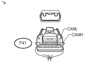
(b) Disconnect the F41 power steering ECU assembly connector.
(c) Measure the resistance according to the value(s) in the table below.
Standard Resistance:
|
Tester Connection |
Switch Condition |
Specified Condition |
|---|---|---|
|
F41-1 (CANH) - F41-2 (CANL) |
Ignition switch off |
54 to 69 Ω |
|
*a |
Rear view of wire harness connector (to Power Steering ECU Assembly) |
| OK | |
REPLACE POWER STEERING ECU ASSEMBLY |
| NG | |
REPAIR OR REPLACE CAN BRANCH WIRE OR CONNECTOR (POWER STEERING ECU ASSEMBLY) |
 Short to GND in CAN Bus Line
DESCRIPTION
There may be a short circuit between the CAN bus lines and GND when the resistance
between terminals 6 (CANH) and 4 (CG) or terminals 14 (CANL) and 4 (CG) of the DLC3
is below 200 Ω. ...

Other materials about Toyota 4Runner:
Precaution
PRECAUTION
1. IGNITION SWITCH EXPRESSION
HINT:
The type of ignition switch used on this model differs according to the specifications
of the vehicle. The expressions listed in the table below are used in this section.
Expression
Ign ...
Back Door Power Window ECU Inner Motor Failure (B2311)
DESCRIPTION
The power window regulator motor is operated by the back door power window regulator
switch. The back power window regulator motor assembly has motor and ECU functions.
This DTC is stored when the back door power window regulator motor assembly ...

0.0077