Toyota 4Runner: Short to GND in CAN Bus Line
DESCRIPTION
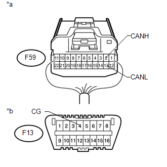
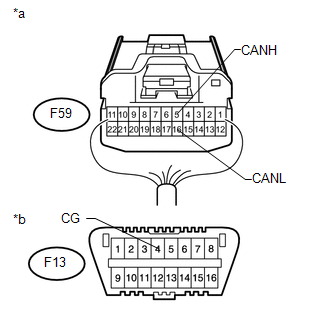
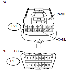
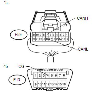
There may be a short circuit between the CAN bus lines and GND when the resistance between terminals 6 (CANH) and 4 (CG) or terminals 14 (CANL) and 4 (CG) of the DLC3 is below 200 Ω.
|
Symptom |
Trouble Area |
|---|---|
|
The resistance between terminals 6 (CANH) and 4 (CG) or terminals 14 (CANL) and 4 (CG) of the DLC3 is below 200 Ω. |
|
- *1: for 4WD
- *2: for Navigation Receiver Type
- *3: for Radio and Display Receiver Type
- *4: w/ Smart Key System
- *5: for 2WD
- *6: w/ Kinetic Dynamic Suspension System
- *7: w/o Smart Key System
WIRING DIAGRAM
.png)
.png)
.png)
.png)
CAUTION / NOTICE / HINT
HINT:
Operating the ignition switch, any switches or any doors triggers related ECU and sensor communication with the CAN, which causes resistance variation.
PROCEDURE
|
1. |
DISCONNECT CABLE FROM NEGATIVE BATTERY TERMINAL |
(a) Disconnect the cable from the negative (-) battery terminal before measuring the resistances of the main wire and branch wire.
CAUTION:
Wait at least 90 seconds after disconnecting the cable from the negative (-) battery terminal to disable the SRS system.
NOTICE:
When disconnecting the cable, some systems need to be initialized after the cable
is reconnected (See page .gif) ).
).
|
.gif)
|
2. |
CHECK FOR SHORT TO GND IN CAN BUS WIRE (DLC3 BRANCH WIRE) |
|
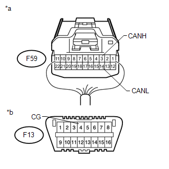
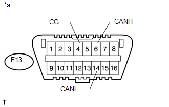
(a) Disconnect the F59 No. 2 junction connector connector. |
|
(b) Measure the resistance according to the value(s) in the table below.
Standard Resistance:
|
Tester Connection |
Switch Condition |
Specified Condition |
|---|---|---|
|
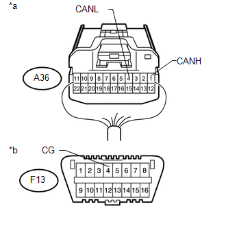
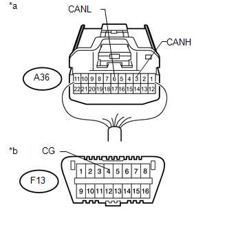
F13-6 (CANH) - F13-4 (CG) |
Ignition switch off |
200 Ω or higher |
|
F13-14 (CANL) - F13-4 (CG) |
Ignition switch off |
200 Ω or higher |
|
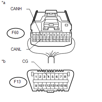
*a |
Front view of DLC3 |
|
Result |
Proceed to |
|---|---|
|
OK (for 4WD) |
A |
|
OK (for 2WD) |
B |
|
NG |
C |
| B | .gif) |
GO TO STEP 13 |
| C | |
REPAIR OR REPLACE CAN BRANCH WIRE CONNECTED TO DLC3 (CANH, CANL) |
|
|
3. |
CONNECT CONNECTOR |
(a) Reconnect the F59 No. 2 junction connector connector.
|
|
4. |
CHECK FOR SHORT TO GND IN CAN BUS WIRE (NO. 1 JUNCTION CONNECTOR SIDE) |
|
(a) Disconnect the A36 No. 1 junction connector connector. |
|
(b) Measure the resistance according to the value(s) in the table below.
Standard Resistance:
|
Tester Connection |
Switch Condition |
Specified Condition |
|---|---|---|
|
F13-6 (CANH) - F13-4 (CG) |
Ignition switch off |
200 Ω or higher |
|
F13-14 (CANL) - F13-4 (CG) |
Ignition switch off |
200 Ω or higher |
|
*a |
Front view of DLC3 |
| NG | |
GO TO STEP 11 |
|
|
5. |
CHECK FOR SHORT TO GND IN CAN BUS WIRE (NO. 1 JUNCTION CONNECTOR - SKID CONTROL ECU (MASTER CYLINDER SOLENOID)) |
|
(a) Measure the resistance according to the value(s) in the table below. Standard Resistance:
|
|
| NG | |
GO TO STEP 7 |
|
|
6. |
CHECK FOR SHORT TO GND IN CAN BUS WIRE (NO. 1 JUNCTION CONNECTOR - COMBINATION METER ASSEMBLY) |
|
(a) Measure the resistance according to the value(s) in the table below. Standard Resistance:
|
|
| OK | |
REPAIR OR REPLACE NO. 1 JUNCTION CONNECTOR |
| NG | |
GO TO STEP 9 |
|
7. |
CONNECT CONNECTOR |
(a) Reconnect the A36 No. 1 junction connector connector.
|
|
8. |
CHECK FOR SHORT TO GND IN CAN BUS WIRE (SKID CONTROL ECU (MASTER CYLINDER SOLENOID)) |
|
(a) Disconnect the A6 skid control ECU (master cylinder solenoid) connector. |
|
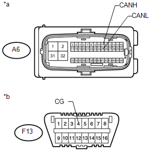
(b) Measure the resistance according to the value(s) in the table below.
Standard Resistance:
|
Tester Connection |
Switch Condition |
Specified Condition |
|---|---|---|
|
A6-11 (CANH) - F13-4 (CG) |
Ignition switch off |
200 Ω or higher |
|
A6-25 (CANL) - F13-4 (CG) |
Ignition switch off |
200 Ω or higher |
|
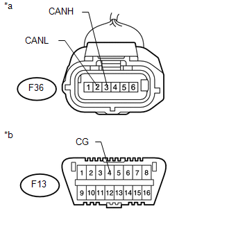
*a |
Front view of wire harness connector (to Skid Control ECU (Master Cylinder Solenoid)) |
|
*b |
Front view of DLC3 |
| OK | |
REPLACE SKID CONTROL ECU (MASTER CYLINDER SOLENOID) |
| NG | |
REPAIR OR REPLACE CAN BRANCH WIRE CONNECTED TO SKID CONTROL ECU (MASTER CYLINDER SOLENOID) (CANH, CANL) |
|
9. |
CONNECT CONNECTOR |
(a) Reconnect the A36 No. 1 junction connector connector.
|
|
10. |
CHECK FOR SHORT TO GND IN CAN BUS WIRE (COMBINATION METER ASSEMBLY) |
|
(a) Disconnect the F14 combination meter assembly connector. |
|
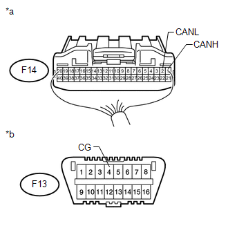
(b) Measure the resistance according to the value(s) in the table below.
Standard Resistance:
|
Tester Connection |
Switch Condition |
Specified Condition |
|---|---|---|
|
F14-1 (CANH) - F13-4 (CG) |
Ignition switch off |
200 Ω or higher |
|
F14-2 (CANL) - F13-4 (CG) |
Ignition switch off |
200 Ω or higher |
|
*a |
Rear view of wire harness connector (to Combination Meter Assembly) |
|
*b |
Front view of DLC3 |
| OK | |
REPLACE COMBINATION METER ASSEMBLY |
| NG | |
REPAIR OR REPLACE CAN MAIN WIRE CONNECTED TO COMBINATION METER ASSEMBLY (CANH, CANL) |
|
11. |
CONNECT CONNECTOR |
(a) Reconnect the A36 No. 1 junction connector connector.
|
|
12. |
CHECK FOR SHORT TO GND IN CAN BUS WIRE (NO. 2 JUNCTION CONNECTOR - NO. 1 JUNCTION CONNECTOR) |
|
(a) Disconnect the F59 No. 2 junction connector connector. |
|
(b) Measure the resistance according to the value(s) in the table below.
Standard Resistance:
|
Tester Connection |
Switch Condition |
Specified Condition |
|---|---|---|
|
F59-3 (CANH) - F13-4 (CG) |
Ignition switch off |
200 Ω or higher |
|
F59-14 (CANL) - F13-4 (CG) |
Ignition switch off |
200 Ω or higher |
|
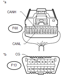
*a |
Rear view of wire harness connector (to No. 2 Junction Connector) |
|
*b |
Front view of DLC3 |
| NG | |
REPAIR OR REPLACE CAN MAIN WIRE OR CONNECTOR (NO. 2 JUNCTION CONNECTOR - NO. 1 JUNCTION CONNECTOR) |
|
|
13. |
CONNECT CONNECTOR |
(a) Reconnect the F59 No. 2 junction connector connector.
|
|
14. |
CHECK FOR SHORT TO GND IN CAN BUS WIRE (NO. 3 JUNCTION CONNECTOR SIDE) |
|
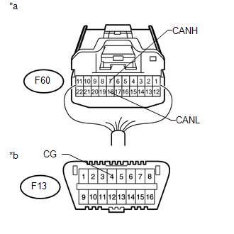
(a) Disconnect the F60 No. 3 junction connector connector. |
|
(b) Measure the resistance according to the value(s) in the table below.
Standard Resistance:
|
Tester Connection |
Switch Condition |
Specified Condition |
|---|---|---|
|
F13-6 (CANH) - F13-4 (CG) |
Ignition switch off |
200 Ω or higher |
|
F13-14 (CANL) - F13-4 (CG) |
Ignition switch off |
200 Ω or higher |
|
*a |
Front view of DLC3 |
| NG | |
GO TO STEP 39 |
|
|
15. |
CHECK FOR SHORT TO GND IN CAN BUS WIRE (NO. 3 JUNCTION CONNECTOR - CERTIFICATION ECU (SMART KEY ECU ASSEMBLY)) |
HINT:
For vehicles without a smart key system, go to "Check for Short to GND in CAN Bus Wire (No. 3 Junction Connector - Power Steering ECU Assembly)".
|
(a) Measure the resistance according to the value(s) in the table below. Standard Resistance:
|
|

| NG | |
GO TO STEP 23 |
|
|
16. |
CHECK FOR SHORT TO GND IN CAN BUS WIRE (NO. 3 JUNCTION CONNECTOR - POWER STEERING ECU ASSEMBLY) |
|
(a) Measure the resistance according to the value(s) in the table below. Standard Resistance:
|
|

| NG | |
GO TO STEP 25 |
|
|
17. |
CHECK FOR SHORT TO GND IN CAN BUS WIRE (NO. 3 JUNCTION CONNECTOR - YAW RATE SENSOR ASSEMBLY) |
|
(a) Measure the resistance according to the value(s) in the table below. Standard Resistance:
|
|
| NG | |
GO TO STEP 27 |
|
|
18. |
CHECK FOR SHORT TO GND IN CAN BUS WIRE (NO. 3 JUNCTION CONNECTOR - POWER MANAGEMENT CONTROL ECU) |
HINT:
For vehicles without a smart key system, go to "Check for Short to GND in CAN Bus Wire (No. 3 Junction Connector - Four Wheel Drive Control ECU)".
|
(a) Measure the resistance according to the value(s) in the table below. Standard Resistance:
|
|
| NG | |
GO TO STEP 29 |
|
|
19. |
CHECK FOR SHORT TO GND IN CAN BUS WIRE (NO. 3 JUNCTION CONNECTOR - FOUR WHEEL DRIVE CONTROL ECU) |
HINT:
For 2WD vehicles, go to "Check for Short to GND in CAN Bus Wire (No. 3 Junction Connector - Skid Control ECU (Brake Actuator Assembly))".
|
(a) Measure the resistance according to the value(s) in the table below. Standard Resistance:
|
|
| NG | |
GO TO STEP 31 |
|
|
20. |
CHECK FOR SHORT TO GND IN CAN BUS WIRE (NO. 3 JUNCTION CONNECTOR - SKID CONTROL ECU (BRAKE ACTUATOR ASSEMBLY)) |
HINT:
For 4WD vehicles, go to "Check for Short to GND in CAN Bus Wire (No. 3 Junction Connector - Air Conditioning Amplifier Assembly)".
|
(a) Measure the resistance according to the value(s) in the table below. Standard Resistance:
|
|
| NG | |
GO TO STEP 33 |
|
|
21. |
CHECK FOR SHORT TO GND IN CAN BUS WIRE (NO. 3 JUNCTION CONNECTOR - AIR CONDITIONING AMPLIFIER ASSEMBLY) |
HINT:
For vehicles with a smart key system, go to "Check for Short to GND in CAN Bus Wire (No. 3 Junction Connector - ECM)".
|
(a) Measure the resistance according to the value(s) in the table below. Standard Resistance:
|
|
| NG | |
GO TO STEP 35 |
|
|
22. |
CHECK FOR SHORT TO GND IN CAN BUS WIRE (NO. 3 JUNCTION CONNECTOR - ECM) |
|
(a) Measure the resistance according to the value(s) in the table below. Standard Resistance:
|
|

| OK | |
REPAIR OR REPLACE NO. 3 JUNCTION CONNECTOR |
| NG | |
GO TO STEP 37 |
|
23. |
CONNECT CONNECTOR |
(a) Reconnect the F60 No. 3 junction connector connector.
|
|
24. |
CHECK FOR SHORT TO GND IN CAN BUS WIRE (CERTIFICATION ECU (SMART KEY ECU ASSEMBLY)) |
|
(a) Disconnect the F79 certification ECU (smart key ECU assembly) connector. |
|
(b) Measure the resistance according to the value(s) in the table below.
Standard Resistance:
|
Tester Connection |
Switch Condition |
Specified Condition |
|---|---|---|
|
F79-9 (CANH) - F13-4 (CG) |
Ignition switch off |
200 Ω or higher |
|
F79-10 (CANL) - F13-4 (CG) |
Ignition switch off |
200 Ω or higher |
|
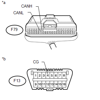
*a |
Rear view of wire harness connector (to Certification ECU (Smart Key ECU Assembly)) |
|
*b |
Front view of DLC3 |
| OK | |
REPLACE CERTIFICATION ECU (SMART KEY ECU ASSEMBLY) |
| NG | |
REPAIR OR REPLACE CAN BRANCH WIRE CONNECTED TO CERTIFICATION ECU (SMART KEY ECU ASSEMBLY) (CANH, CANL) |
|
25. |
CONNECT CONNECTOR |
(a) Reconnect the F60 No. 3 junction connector connector.
|
|
26. |
CHECK FOR SHORT TO GND IN CAN BUS WIRE (POWER STEERING ECU ASSEMBLY) |
|
(a) Disconnect the F41 power steering ECU assembly connector. |
|
(b) Measure the resistance according to the value(s) in the table below.
Standard Resistance:
|
Tester Connection |
Switch Condition |
Specified Condition |
|---|---|---|
|
F41-1 (CANH) - F13-4 (CG) |
Ignition switch off |
200 Ω or higher |
|
F41-2 (CANL) - F13-4 (CG) |
Ignition switch off |
200 Ω or higher |
|
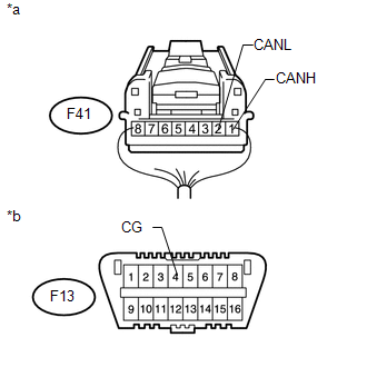
*a |
Rear view of wire harness connector (to Power Steering ECU Assembly) |
|
*b |
Front view of DLC3 |
| OK | |
REPLACE POWER STEERING ECU ASSEMBLY |
| NG | |
REPAIR OR REPLACE CAN BRANCH WIRE CONNECTED TO POWER STEERING ECU ASSEMBLY (CANH, CANL) |
|
27. |
CONNECT CONNECTOR |
(a) Reconnect the F60 No. 3 junction connector connector.
|
|
28. |
CHECK FOR SHORT TO GND IN CAN BUS WIRE (YAW RATE SENSOR ASSEMBLY) |
|
(a) Disconnect the F36 yaw rate sensor assembly connector. |
|
(b) Measure the resistance according to the value(s) in the table below.
Standard Resistance:
|
Tester Connection |
Switch Condition |
Specified Condition |
|---|---|---|
|
F36-3 (CANH) - F13-4 (CG) |
Ignition switch off |
200 Ω or higher |
|
F36-2 (CANL) - F13-4 (CG) |
Ignition switch off |
200 Ω or higher |
|
*a |
Front view of wire harness connector (to Yaw Rate Sensor Assembly) |
|
*b |
Front view of DLC3 |
| OK | |
REPLACE YAW RATE SENSOR ASSEMBLY |
| NG | |
REPAIR OR REPLACE CAN BRANCH WIRE CONNECTED TO YAW RATE SENSOR ASSEMBLY (CANH, CANL) |
|
29. |
CONNECT CONNECTOR |
(a) Reconnect the F60 No. 3 junction connector connector.
|
|
30. |
CHECK FOR SHORT TO GND IN CAN BUS WIRE (POWER MANAGEMENT CONTROL ECU) |
|
(a) Disconnect the F80 power management control ECU connector. |
|
(b) Measure the resistance according to the value(s) in the table below.
Standard Resistance:
|
Tester Connection |
Switch Condition |
Specified Condition |
|---|---|---|
|
F80-14 (CA1H) - F13-4 (CG) |
Ignition switch off |
200 Ω or higher |
|
F80-13 (CA1L) - F13-4 (CG) |
Ignition switch off |
200 Ω or higher |
|
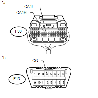
*a |
Rear view of wire harness connector (to Power Management Control ECU) |
|
*b |
Front view of DLC3 |
| OK | |
REPLACE POWER MANAGEMENT CONTROL ECU |
| NG | |
REPAIR OR REPLACE CAN BRANCH WIRE CONNECTED TO POWER MANAGEMENT CONTROL ECU (CA1H, CA1L) |
|
31. |
CONNECT CONNECTOR |
(a) Reconnect the F60 No. 3 junction connector connector.
|
|
32. |
CHECK FOR SHORT TO GND IN CAN BUS WIRE (FOUR WHEEL DRIVE CONTROL ECU) |
|
(a) Disconnect the F47 four wheel drive control ECU connector. |
|
(b) Measure the resistance according to the value(s) in the table below.
Standard Resistance:
|
Tester Connection |
Switch Condition |
Specified Condition |
|---|---|---|
|
F47-19 (CANH) - F13-4 (CG) |
Ignition switch off |
200 Ω or higher |
|
F47-20 (CANL) - F13-4 (CG) |
Ignition switch off |
200 Ω or higher |
|
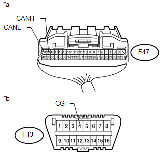
*a |
Rear view of wire harness connector (to Four Wheel Drive Control ECU) |
|
*b |
Front view of DLC3 |
|
Result |
Proceed to |
|---|---|
|
OK (for VF2A) |
A |
|
OK (for VF4BM) |
B |
|
OK (for VF2BM) |
C |
|
NG |
D |
| A | |
REPLACE FOUR WHEEL DRIVE CONTROL ECU |
| B | |
REPLACE FOUR WHEEL DRIVE CONTROL ECU |
| C | |
REPLACE FOUR WHEEL DRIVE CONTROL ECU |
| D | |
REPAIR OR REPLACE CAN BRANCH WIRE CONNECTED TO FOUR WHEEL DRIVE CONTROL ECU (CANH, CANL) |
|
33. |
CONNECT CONNECTOR |
(a) Reconnect the F60 No. 3 junction connector connector.
|
|
34. |
CHECK FOR SHORT TO GND IN CAN BUS WIRE (SKID CONTROL ECU (BRAKE ACTUATOR ASSEMBLY)) |
|
(a) Disconnect the A53 skid control ECU (brake actuator assembly) connector. |
|
(b) Measure the resistance according to the value(s) in the table below.
Standard Resistance:
|
Tester Connection |
Switch Condition |
Specified Condition |
|---|---|---|
|
A53-25 (CANH) - F13-4 (CG) |
Ignition switch off |
200 Ω or higher |
|
A53-14 (CANL) - F13-4 (CG) |
Ignition switch off |
200 Ω or higher |
|
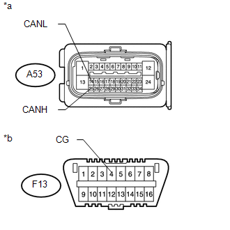
*a |
Front view of wire harness connector (to Skid Control ECU (Brake Actuator Assembly)) |
|
*b |
Front view of DLC3 |
| OK | |
REPLACE SKID CONTROL ECU (BRAKE ACTUATOR ASSEMBLY) |
| NG | |
REPAIR OR REPLACE CAN BRANCH WIRE CONNECTED TO SKID CONTROL ECU (BRAKE ACTUATOR ASSEMBLY) (CANH, CANL) |
|
35. |
CONNECT CONNECTOR |
(a) Reconnect the F60 No. 3 junction connector connector.
|
|
36. |
CHECK FOR SHORT TO GND IN CAN BUS WIRE (AIR CONDITIONING AMPLIFIER ASSEMBLY) |
|
(a) Disconnect the F42 air conditioning amplifier assembly connector. |
|
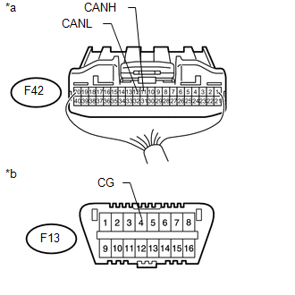
(b) Measure the resistance according to the value(s) in the table below.
Standard Resistance:
|
Tester Connection |
Switch Condition |
Specified Condition |
|---|---|---|
|
F42-11 (CANH) - F13-4 (CG) |
Ignition switch off |
200 Ω or higher |
|
F42-12 (CANL) - F13-4 (CG) |
Ignition switch off |
200 Ω or higher |
|
*a |
Rear view of wire harness connector (to Air Conditioning Amplifier Assembly) |
|
*b |
Front view of DLC3 |
| OK | |
REPLACE AIR CONDITIONING AMPLIFIER ASSEMBLY |
| NG | |
REPAIR OR REPLACE CAN BRANCH WIRE CONNECTED TO AIR CONDITIONING AMPLIFIER ASSEMBLY (CANH, CANL) |
|
37. |
CONNECT CONNECTOR |
(a) Reconnect the F60 No. 3 junction connector connector.
|
|
38. |
CHECK FOR SHORT TO GND IN CAN BUS WIRE (ECM) |
(a) Disconnect the F50 ECM connector.
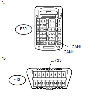
(b) Measure the resistance according to the value(s) in the table below.
Standard Resistance:
|
Tester Connection |
Switch Condition |
Specified Condition |
|---|---|---|
|
F50-32 (CANH) - F13-4 (CG) |
Ignition switch off |
200 Ω or higher |
|
F50-31 (CANL) - F13-4 (CG) |
Ignition switch off |
200 Ω or higher |
|
*a |
Rear view of wire harness connector (to ECM) |
|
*b |
Front view of DLC3 |
| OK | |
REPLACE ECM |
| NG | |
REPAIR OR REPLACE CAN MAIN WIRE CONNECTED TO ECM (CANH, CANL) |
|
39. |
CONNECT CONNECTOR |
(a) Reconnect the F60 No. 3 junction connector connector.
|
|
40. |
CHECK FOR SHORT TO GND IN CAN BUS WIRE (NO. 4 JUNCTION CONNECTOR SIDE) |
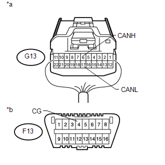
(a) Disconnect the G13 No. 4 junction connector connector.
(b) Measure the resistance according to the value(s) in the table below.
Standard Resistance:
|
Tester Connection |
Switch Condition |
Specified Condition |
|---|---|---|
|
F13-6 (CANH) - F13-4 (CG) |
Ignition switch off |
200 Ω or higher |
|
F13-14 (CANL) - F13-4 (CG) |
Ignition switch off |
200 Ω or higher |
|
*a |
Front view of DLC3 |
| NG | |
GO TO STEP 48 |
|
|
41. |
CHECK FOR SHORT TO GND IN CAN BUS WIRE (NO. 4 JUNCTION CONNECTOR - NO. 3 JUNCTION CONNECTOR) |
|
(a) Measure the resistance according to the value(s) in the table below. |
|
Standard Resistance:
|
Tester Connection |
Switch Condition |
Specified Condition |
|---|---|---|
|
G13-5 (CANH) - F13-4 (CG) |
Ignition switch off |
200 Ω or higher |
|
G13-16 (CANL) - F13-4 (CG) |
Ignition switch off |
200 Ω or higher |
|
*a |
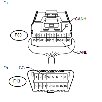
Rear view of wire harness connector (to No. 4 Junction Connector) |
|
*b |
Front view of DLC3 |
| NG | |
REPAIR OR REPLACE CAN MAIN WIRE OR CONNECTOR (NO. 4 JUNCTION CONNECTOR - NO. 3 JUNCTION CONNECTOR) |
|
|
42. |
CHECK FOR SHORT TO GND IN CAN BUS WIRE (NO. 4 JUNCTION CONNECTOR - NAVIGATION RECEIVER ASSEMBLY) |
HINT:
For vehicles without a navigation receiver assembly, go to "Check for Short to GND in CAN Bus Wire (No. 4 Junction Connector - Radio and Display Receiver Assembly)".
|
(a) Disconnect the G14 No. 4 junction connector connector. |
|
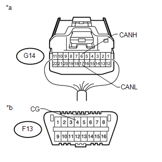
(b) Measure the resistance according to the value(s) in the table below.
Standard Resistance:
|
Tester Connection |
Switch Condition |
Specified Condition |
|---|---|---|
|
G14-6 (CANH) - F13-4 (CG) |
Ignition switch off |
200 Ω or higher |
|
G14-17 (CANL) - F13-4 (CG) |
Ignition switch off |
200 Ω or higher |
|
*a |
Rear view of wire harness connector (to No. 4 Junction Connector) |
|
*b |
Front view of DLC3 |
| NG | |
GO TO STEP 44 |
|
|
43. |
CHECK FOR SHORT TO GND IN CAN BUS WIRE (NO. 4 JUNCTION CONNECTOR - RADIO AND DISPLAY RECEIVER ASSEMBLY) |
|
(a) Disconnect the G14 No. 4 junction connector connector. |
|
(b) Measure the resistance according to the value(s) in the table below.
Standard Resistance:
|
Tester Connection |
Switch Condition |
Specified Condition |
|---|---|---|
|
G14-6 (CANH) - F13-4 (CG) |
Ignition switch off |
200 Ω or higher |
|
G14-17 (CANL) - F13-4 (CG) |
Ignition switch off |
200 Ω or higher |
|
*a |
Rear view of wire harness connector (to No. 4 Junction Connector) |
|
*b |
Front view of DLC3 |
| OK | |
REPAIR OR REPLACE NO. 4 JUNCTION CONNECTOR |
| NG | |
GO TO STEP 46 |
|
44. |
CONNECT CONNECTOR |
(a) Reconnect the G13 and G14 No. 4 junction connector connectors.
|
|
45. |
CHECK FOR SHORT TO GND IN CAN BUS WIRE (NAVIGATION RECEIVER ASSEMBLY) |
(a) Disconnect the G37 navigation receiver assembly connector.
|
(b) Measure the resistance according to the value(s) in the table below. Standard Resistance:
|
|
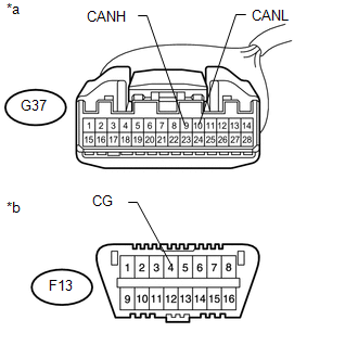
| OK | |
REPLACE NAVIGATION RECEIVER ASSEMBLY |
| NG | |
REPAIR OR REPLACE CAN BRANCH WIRE CONNECTED TO NAVIGATION RECEIVER ASSEMBLY (CANH, CANL) |
|
46. |
CONNECT CONNECTOR |
(a) Reconnect the G13 and G14 No. 4 junction connector connectors.
|
|
47. |
CHECK FOR SHORT TO GND IN CAN BUS WIRE (RADIO AND DISPLAY RECEIVER ASSEMBLY) |
(a) Disconnect the G49 radio and display receiver assembly connector.
|
(b) Measure the resistance according to the value(s) in the table below. Standard Resistance:
|
|
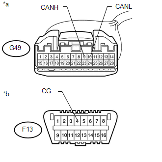
| OK | |
REPLACE RADIO AND DISPLAY RECEIVER ASSEMBLY |
| NG | |
REPAIR OR REPLACE CAN BRANCH WIRE CONNECTED TO RADIO AND DISPLAY RECEIVER ASSEMBLY (CANH, CANL) |
|
48. |
CONNECT CONNECTOR |
(a) Reconnect the G13 No. 4 junction connector connector.
|
|
49. |
CHECK FOR SHORT TO GND IN CAN BUS WIRE (NO. 2 JUNCTION CONNECTOR - NO. 4 JUNCTION CONNECTOR) |
|
(a) Disconnect the F59 No. 2 junction connector connector. |
|
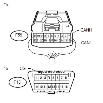
(b) Measure the resistance according to the value(s) in the table below.
Standard Resistance:
|
Tester Connection |
Switch Condition |
Specified Condition |
|---|---|---|
|
F59-1 (CANH) - F13-4 (CG) |
Ignition switch off |
200 Ω or higher |
|
F59-12 (CANL) - F13-4 (CG) |
Ignition switch off |
200 Ω or higher |
|
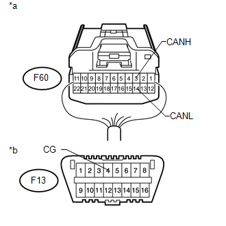
*a |
Rear view of wire harness connector (to No. 2 Junction Connector) |
|
*b |
Front view of DLC3 |
| NG | |
REPAIR OR REPLACE CAN MAIN WIRE OR CONNECTOR (NO. 2 JUNCTION CONNECTOR - NO. 4 JUNCTION CONNECTOR) |
|
|
50. |
CHECK FOR SHORT TO GND IN CAN BUS WIRE (NO. 2 JUNCTION CONNECTOR - MAIN BODY ECU (MULTIPLEX NETWORK BODY ECU)) |
|
(a) Measure the resistance according to the value(s) in the table below. Standard Resistance:
|
|
| NG | |
GO TO STEP 55 |
|
|
51. |
CHECK FOR SHORT TO GND IN CAN BUS WIRE (NO. 2 JUNCTION CONNECTOR - AIRBAG SENSOR ASSEMBLY) |
|
(a) Measure the resistance according to the value(s) in the table below. Standard Resistance:
|
|
| NG | |
GO TO STEP 57 |
|
|
52. |
CHECK FOR SHORT TO GND IN CAN BUS WIRE (NO. 2 JUNCTION CONNECTOR - STABILIZER CONTROL ECU) |
HINT:
For vehicles without a kinetic dynamic suspension system, go to "Check for Short to GND in CAN Bus Wire (No. 2 Junction Connector - Combination Meter Assembly)".
|
(a) Measure the resistance according to the value(s) in the table below. Standard Resistance:
|
|
| NG | |
GO TO STEP 59 |
|
|
53. |
CHECK FOR SHORT TO GND IN CAN BUS WIRE (NO. 2 JUNCTION CONNECTOR - COMBINATION METER ASSEMBLY) |
HINT:
For 4WD vehicles, go to "Check for Short to GND in CAN Bus Wire (No. 2 Junction Connector - Steering Angle Sensor (Spiral Cable Sub-assembly))".
|
(a) Measure the resistance according to the value(s) in the table below. Standard Resistance:
|
|
| NG | |
GO TO STEP 61 |
|
|
54. |
CHECK FOR SHORT TO GND IN CAN BUS WIRE (NO. 2 JUNCTION CONNECTOR - STEERING ANGLE SENSOR (SPIRAL CABLE SUB-ASSEMBLY)) |
|
(a) Measure the resistance according to the value(s) in the table below. Standard Resistance:
|
|
| OK | |
REPAIR OR REPLACE NO. 2 JUNCTION CONNECTOR |
| NG | |
GO TO STEP 63 |
|
55. |
CONNECT CONNECTOR |
(a) Reconnect the F59 No. 2 junction connector connector.
|
|
56. |
CHECK FOR SHORT TO GND IN CAN BUS WIRE (MAIN BODY ECU (MULTIPLEX NETWORK BODY ECU)) |
|
(a) Disconnect the F9 main body ECU (multiplex network body ECU) connector. |
|
(b) Measure the resistance according to the value(s) in the table below.
Standard Resistance:
|
Tester Connection |
Switch Condition |
Specified Condition |
|---|---|---|
|
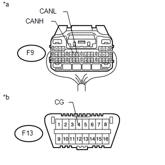
F9-14 (CANH) - F13-4 (CG) |
Ignition switch off |
200 Ω or higher |
|
F9-13 (CANL) - F13-4 (CG) |
Ignition switch off |
200 Ω or higher |
|
*a |
Rear view of wire harness connector (to Main Body ECU (Multiplex Network Body ECU)) |
|
*b |
Front view of DLC3 |
| OK | |
REPLACE MAIN BODY ECU (MULTIPLEX NETWORK BODY ECU) |
| NG | |
REPAIR OR REPLACE CAN BRANCH WIRE CONNECTED TO MAIN BODY ECU (MULTIPLEX NETWORK BODY ECU) (CANH, CANL) |
|
57. |
CONNECT CONNECTOR |
(a) Reconnect the F59 No. 2 junction connector connector.
|
|
58. |
CHECK FOR SHORT TO GND IN CAN BUS WIRE (AIRBAG SENSOR ASSEMBLY) |
|
(a) Disconnect the F33 airbag sensor assembly connector. |
|
(b) Measure the resistance according to the value(s) in the table below.
Standard Resistance:
|
Tester Connection |
Switch Condition |
Specified Condition |
|---|---|---|
|
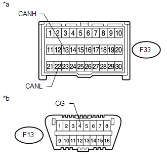
F33-13 (CANH) - F13-4 (CG) |
Ignition switch off |
200 Ω or higher |
|
F33-22 (CANL) - F13-4 (CG) |
Ignition switch off |
200 Ω or higher |
|
*a |
Front view of wire harness connector (to Airbag Sensor Assembly) |
|
*b |
Front view of DLC3 |
| OK | |
REPLACE AIRBAG SENSOR ASSEMBLY |
| NG | |
REPAIR OR REPLACE CAN BRANCH WIRE CONNECTED TO AIRBAG SENSOR ASSEMBLY (CANH, CANL) |
|
59. |
CONNECT CONNECTOR |
(a) Reconnect the F59 No. 2 junction connector connector.
|
|
60. |
CHECK FOR SHORT TO GND IN CAN BUS WIRE (STABILIZER CONTROL ECU) |
|
(a) Disconnect the F70 stabilizer control ECU connector. |
|
(b) Measure the resistance according to the value(s) in the table below.
Standard Resistance:
|
Tester Connection |
Switch Condition |
Specified Condition |
|---|---|---|
|
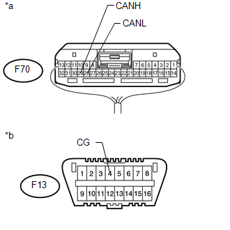
F70-29 (CANH) - F13-4 (CG) |
Ignition switch off |
200 Ω or higher |
|
F70-28 (CANL) - F13-4 (CG) |
Ignition switch off |
200 Ω or higher |
|
*a |
Rear view of wire harness connector (to Stabilizer Control ECU) |
|
*b |
Front view of DLC3 |
| OK | |
REPLACE STABILIZER CONTROL ECU |
| NG | |
REPAIR OR REPLACE CAN BUS BRANCH WIRE CONNECTED TO STABILIZER CONTROL ECU (CANH, CANL) |
|
61. |
CONNECT CONNECTOR |
(a) Reconnect the F59 No. 2 junction connector connector.
|
|
62. |
CHECK FOR SHORT TO GND IN CAN BUS WIRE (COMBINATION METER ASSEMBLY) |
|
(a) Disconnect the F14 combination meter assembly connector. |
|
(b) Measure the resistance according to the value(s) in the table below.
Standard Resistance:
|
Tester Connection |
Switch Condition |
Specified Condition |
|---|---|---|
|
F14-1 (CANH) - F13-4 (CG) |
Ignition switch off |
200 Ω or higher |
|
F14-2 (CANL) - F13-4 (CG) |
Ignition switch off |
200 Ω or higher |
|
*a |
Rear view of wire harness connector (to Combination Meter Assembly) |
|
*b |
Front view of DLC3 |
| OK | |
REPLACE COMBINATION METER ASSEMBLY |
| NG | |
REPAIR OR REPLACE CAN MAIN WIRE CONNECTED TO COMBINATION METER ASSEMBLY (CANH, CANL) |
|
63. |
CONNECT CONNECTOR |
(a) Reconnect the F59 No. 2 junction connector connector.
|
|
64. |
CHECK FOR SHORT TO GND IN CAN BUS WIRE (STEERING ANGLE SENSOR (SPIRAL CABLE SUB-ASSEMBLY)) |
|
(a) Disconnect the F19 steering angle sensor (spiral cable sub-assembly) connector. |
|
(b) Measure the resistance according to the value(s) in the table below.
Standard Resistance:
|
Tester Connection |
Switch Condition |
Specified Condition |
|---|---|---|
|
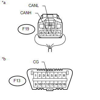
F19-4 (CANH) - F13-4 (CG) |
Ignition switch off |
200 Ω or higher |
|
F19-3 (CANL) - F13-4 (CG) |
Ignition switch off |
200 Ω or higher |
|
*a |
Rear view of wire harness connector (to Steering Angle Sensor (Spiral Cable Sub-assembly)) |
|
*b |
Front view of DLC3 |
| OK | |
REPLACE STEERING ANGLE SENSOR (SPIRAL CABLE SUB-ASSEMBLY) |
| NG | |
REPAIR OR REPLACE CAN BRANCH WIRE CONNECTED TO STEERING ANGLE SENSOR (SPIRAL CABLE SUB-ASSEMBLY) (CANH, CANL) |
 Short to B+ in CAN Bus Line
DESCRIPTION
There may be a short circuit between the CAN bus lines and +B when the resistance
between terminals 6 (CANH) and 16 (BAT) or terminals 14 (CANL) and 16 (BAT) of the
DLC3 is below 6 kÎ ...
 Open in One Side of CAN Branch Line
DESCRIPTION
If 2 or more ECUs and/or sensors do not appear on the Techstream "CAN Bus Check"
screen, one side of the CAN branch wire may be open (one side of the CANH [branch
wire]/CANL ...
Other materials about Toyota 4Runner:
Accumulator Solenoid Malfunction / Upside (C1831/31,C1832/32)
DESCRIPTION
The stabilizer control ECU receives information from the steering angle sensor,
skid control ECU (speed signal) and yaw rate and acceleration sensor via CAN communication.
Based on this information, the stabilizer control ECU turns the stabili ...
Removal
REMOVAL
CAUTION / NOTICE / HINT
HINT:
Use the same procedure for the RH and LH sides.
The procedure listed below is for the LH side.
PROCEDURE
1. DISCONNECT CABLE FROM NEGATIVE BATTERY TERMINAL
NOTICE:
When disconnecting the cable, som ...

0.0289