Toyota 4Runner: Operation Check
OPERATION CHECK
1. INSPECT INDICATOR/WARNING LIGHT
(a) Check the following indicators and warning lights.
|
Indicator/Warning Light |
Switch Condition |
Specified Condition |
|---|---|---|
|
Tire pressure warning light |
Ignition switch off → ON |
Comes on for 3 seconds |
|
SLIP indicator light |
||
|
VSC OFF indicator light |
||
|
AUTO LSD indicator light*1 |
||
|
A-TRAC indicator light*2 |
||
|
CRAWL indicator light*3 |
||
|
Downhill assist control indicator light*4 |
||
|
TRAC OFF indicator light |
||
|
ABS warning light |
||
|
BRAKE warning light |
||
|
Eco driving indicator light |
||
|
Kinetic dynamic suspension system indicator light*5 |
||
|
PPS warning light |
||
|
Master warning light |
||
|
SRS warning light |
Ignition switch off → ON |
Comes on for 6 seconds |
|
OIL PRESSURE warning light |
Ignition switch off → ON |
|
|
MIL |
||
|
CHARGE warning light |
- *1: for 2WD
- *2: for 4WD
- *3: w/ CRAWL Control
- *4: w/ Downhill Assist Control System
- *5: w/ Kinetic Dynamic Suspension System
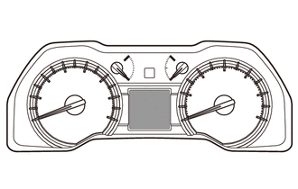
2. INSPECT SPEEDOMETER
(a) Connect the Techstream to the DLC3.
(b) Turn the ignition switch to ON.
(c) Turn the Techstream on.
(d) Enter the following menus: Chassis / ABS/VSC/TRAC / Data List / Vehicle Speed.
(e) According to the display on Techstream, read the Data List.
Reference:
mph (for U.S.A.)|
Techstream Display (mph) |
Speedometer Display (mph) |
|---|---|
|
20 |
19.2 to 21.7 |
|
40 |
39.5 to 42.3 |
|
60 |
59.9 to 62.7 |
|
80 |
80.1 to 83.3 |
|
100 |
100.5 to 103.7 |
|
Techstream Display |
Speedometer Display (km/h) |
|---|---|
|
20 |
18.4 to 22.4 |
|
40 |
38.7 to 43.2 |
|
60 |
59.1 to 63.6 |
|
80 |
79.2 to 84.2 |
|
100 |
99.6 to 104.6 |
|
120 |
120.1 to 125.1 |
|
140 |
140.5 to 143.5 |
|
160 |
160.9 to 165.9 |
|
180 |
181.4 to 186.4 |
If the result is not as specified, the speedometer may have a malfunction.
NOTICE:
Do not use worn, underinflated or overinflated tires, as the speedometer reading will be inaccurate.
(f) Check the deflection width of the speedometer indicator.
Reference:
Within 0.3°
3. INSPECT TACHOMETER
(a) Connect the Techstream to the DLC3.
(b) Turn the ignition switch to ON.
(c) Turn the Techstream on.
(d) Enter the following menus: Powertrain / Engine and ECT / Data List / Engine Speed.
(e) Connect the Techstream and start the engine.
(f) According to the display on Techstream, read the Data List.
DC 13.5 V, at 25°C (77°F):
|
Techstream Display (rpm) |
Acceptable Range Data in ( ) is for Reference |
|---|---|
|
700 |
630 to 770 |
|
1000 |
(900 to 1100) |
|
2000 |
(1850 to 2150) |
|
3000 |
2800 to 3200 |
|
4000 |
(3800 to 4200) |
|
5000 |
4800 to 5200 |
|
6000 |
(5750 to 6250) |
If the result is not as specified, the tachometer may have a malfunction.
4. INSPECT METER/GAUGE
(a) Connect the Techstream to the DLC3.
(b) Perform the Active Test (See page .gif) ).
).
OK:
Each meter/gauge needle indication is normal.
5. INSPECT WARNING/INDICATOR LIGHT
(a) Connect the Techstream to the DLC3.
(b) Perform the Active Test (See page ).
OK:
Each warning/indicator light can be turned on and off using the Techstream.
6. INSPECT MULTI-INFORMATION DISPLAY
(a) Connect the Techstream to the DLC3.
(b) Perform the Active Test (See page ).
HINT:
If this Active Test is being performed and the ignition switch is turned off and then to ON, the clock and ODO/TRIP display background may turn white. If this occurs, end the Active Test and turn the ignition switch off.
OK:
All dots in the multi-information display can be turned on and off using the Techstream.
 Customize Parameters
CUSTOMIZE PARAMETERS
1. METER/GAUGE SYSTEM
(a) Combination Meter
NOTICE:
Record the current settings before customizing.
When the customer requests a change in a function, first make s ...
 Calibration
CALIBRATION
Initial Calibration of Compass:
The compass indicates the direction that the vehicle is heading by detecting
the direction and strength of the earth's magnetic field and processing ...
Other materials about Toyota 4Runner:
Installation
INSTALLATION
PROCEDURE
1. INSTALL PROPELLER SHAFT ASSEMBLY
(a) Remove SST from the extension housing.
SST: 09325-40010
(b) Install the propeller shaft assembly to the extension housing.
(c) Align the matchmarks on the propeller shaft flange and different ...
Installation
INSTALLATION
CAUTION / NOTICE / HINT
HINT:
A bolt without a torque specification is shown in the standard bolt chart (See
page ).
PROCEDURE
1. INSTALL DECK SIDE TRIM CUP HOLDER LH (w/ Rear No. 2 Seat)
(a) Attach the 2 claws to install the deck side tr ...

0.0073