Toyota 4Runner: Reassembly
REASSEMBLY
PROCEDURE
1. INSTALL MAGNET CLUTCH ASSEMBLY
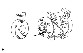
(a) Align the parts as shown in the illustration and install the magnet clutch stator.
|
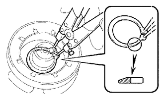
(b) Using a snap ring expander, install a new snap ring with the chamfered side facing up. |
|
(c) Connect the connector.
|
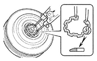
(d) Using a snap ring expander, install the magnet clutch rotor and a new snap ring with the chamfered side facing up. NOTICE: Do not damage the seal cover of the bearing when installing the snap ring. |
|
(e) Install the compressor washer(s) and magnet clutch hub.
NOTICE:
Do not change the combination of compressor washer(s) used before disassembly.
|
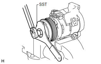
(f) Using SST, hold the magnet clutch hub and install the bolt. SST: 07112-76060 Torque: 18 N·m {184 kgf·cm, 13 ft·lbf} NOTICE: Make sure that there is no foreign matter or oil on the compressor shaft, bolt and clutch hub. |
|
2. INSTALL COOLER BRACKET
(a) Install the cooler bracket with the screw.
(b) Attach the clamp.
3. INSPECT MAGNET CLUTCH CLEARANCE

(a) Clamp the cooler compressor in a vise.
(b) Set a dial indicator on the magnet clutch hub.
(c) Connect the positive (+) lead of the battery to terminal 3 of the magnet clutch connector and the negative (-) lead to the ground wire. Turn the magnet clutch on and off and measure the clearance.
Standard clearance:
0.35 to 0.60 mm (0.014 to 0.024 in.)
Text in Illustration|
*1 |
Battery |
|
*a |
Component without harness connected (Magnet Clutch Assembly) |
If the measured value is not within the standard range, remove the magnet clutch hub and adjust the clearance using compressor washers to obtain the standard clearance.
Compressor washer thickness:
0.1 mm (0.004 in.)
0.3 mm (0.012 in.)
0.5 mm (0.020 in.)
NOTICE:
Be sure to perform the adjustment with 3 or fewer magnet clutch washers.
(d) Remove the cooler compressor from the vise.
 Installation
INSTALLATION
PROCEDURE
1. ADJUST COMPRESSOR OIL
(a) When replacing the compressor and magnetic clutch with a new one, gradually
discharge the refrigerant gas from the service valve and drain the ...
 Condenser
...
Other materials about Toyota 4Runner:
Extension Housing Rear Oil Seal
Components
COMPONENTS
ILLUSTRATION
Replacement
REPLACEMENT
PROCEDURE
1. REMOVE PROPELLER SHAFT ASSEMBLY
(a) Remove the propeller shaft (See page ).
2. REMOVE AUTOMATIC TRANSMISSION EXTENSION HOUSING OIL SEAL
(a) Using SST, remove the oil seal ...
Inspection
INSPECTION
PROCEDURE
1. INSPECT BACK DOOR POWER WINDOW REGULATOR MOTOR ASSEMBLY
(a) Check that the motor gear rotates smoothly as follows.
NOTICE:
Do not apply positive (+) battery voltage to any terminals except terminal
2 (B) to avoid ...

0.008