Toyota 4Runner: Installation
INSTALLATION
PROCEDURE
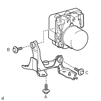
1. INSTALL BRAKE ACTUATOR BOLT CUSHION
(a) Install the 3 brake actuator bolt cushions to the brake actuator bracket.
2. INSTALL BRAKE ACTUATOR CASE COLLAR
(a) Install the 3 brake actuator case collars to the brake actuator bolt cushions.
NOTICE:
Make sure the collars are in full contact with the cushions.
3. INSTALL BRAKE ACTUATOR BRACKET
|
(a) Install the brake actuator bracket to the brake actuator with the 3 bolts. Tighten the 3 bolts uniformly in alphabetical order. Torque: 5.4 N·m {55 kgf·cm, 48 in·lbf} NOTICE:
|
|
4. INSTALL BRAKE ACTUATOR ASSEMBLY
|
(a) Install the brake actuator with bracket with the 3 nuts. Tighten the 3 nuts uniformly in alphabetical order. Torque: 19 N·m {194 kgf·cm, 14 ft·lbf} NOTICE:
|
|
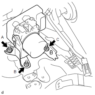
(b) Connect the wire harness bracket with the nut.
Torque:
19 N·m {194 kgf·cm, 14 ft·lbf}
|
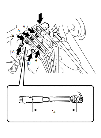
(c) Set each brake line in the correct position on the brake actuator as shown in the illustration. HINT:
|
|
.png)
|
(d) Using a union nut wrench, tighten each brake line. Text in Illustration
Torque: Specified tightening torque for flare nut A : 15 N·m {155 kgf·cm, 11 ft·lbf} Specified tightening torque for flare nut B : 20 N·m {199 kgf·cm, 14 ft·lbf} HINT:
|
|
(e) Connect the brake actuator connector.
NOTICE:
- Make sure that the connector is locked securely.
- Make sure that the actuator connector can be connected smoothly. Do not allow water, oil or dirt to enter.
5. BLEED BRAKE SYSTEM
.gif)
6. CONNECT CABLE TO NEGATIVE BATTERY TERMINAL
NOTICE:
When disconnecting the cable, some systems need to be initialized after the cable
is reconnected (See page ).
7. INSPECT BRAKE ACTUATOR USING TECHSTREAM
(See page )
8. PERFORM YAW RATE AND ACCELERATION SENSOR ZERO POINT CALIBRATION
(See page )
 Removal
REMOVAL
PROCEDURE
1. DISCONNECT CABLE FROM NEGATIVE BATTERY TERMINAL
CAUTION:
Wait at least 90 seconds after disconnecting the cable from the negative (-)
battery terminal to disable the SRS sys ...
 Crawl Switch
Components
COMPONENTS
ILLUSTRATION
Removal
REMOVAL
PROCEDURE
1. REMOVE DRIVE MONITOR SWITCH (CRAWL CONTROL SWITCH AND MULTI-TERRAIN SELECT
SWITCH)
(a) Detach the 4 claws and ...
Other materials about Toyota 4Runner:
Lost Communication with Side Satellite Sensor Bus RH (B1642/81,B1647/82)
DESCRIPTION
The circuit for the side collision sensor LH or RH (to determine deployment of
the front seat side airbag LH or RH and curtain shield airbag LH or RH) is composed
of the center airbag sensor, rear airbag sensor LH or RH and side airbag sensor ...
Trailer towing tips
Your vehicle will handle differently when towing a trailer. Help to avoid an
accident, death or serious injury, keep the following in mind when towing:
• Speed limits for towing a trailer vary by state or province. Do not exceed
the posted towing speed ...

0.007