Toyota 4Runner: Rear Door Courtesy Switch
Components
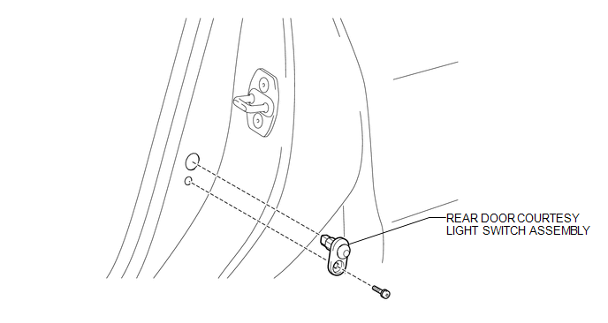
COMPONENTS
ILLUSTRATION
Inspection
INSPECTION
PROCEDURE
1. INSPECT REAR DOOR COURTESY LIGHT SWITCH ASSEMBLY
|
(a) Measure the resistance according to the value(s) in the table below. Standard Resistance:
If the result is not as specified, replace the rear door courtesy light switch assembly. Text in Illustration
|
|
.png)
Removal
REMOVAL
CAUTION / NOTICE / HINT
HINT:
- Use the same procedure for the RH and LH sides.
- The procedure listed below is for the LH side.
PROCEDURE
1. REMOVE REAR DOOR COURTESY LIGHT SWITCH ASSEMBLY
|
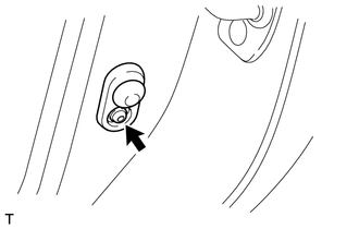
(a) Using a T30 "TORX" socket wrench, remove the screw and courtesy light switch. |
|
(b) Disconnect the connector.
Installation
INSTALLATION
CAUTION / NOTICE / HINT
HINT:
- Use the same procedure for the RH and LH sides.
- The procedure listed below is for the LH side.
PROCEDURE
1. INSTALL REAR DOOR COURTESY LIGHT SWITCH ASSEMBLY
(a) Connect the connector.
(b) Using a T30 "TORX" socket wrench, install the courtesy light switch with the screw.
 Personal Light(for Rear Door)
Components
COMPONENTS
ILLUSTRATION
Removal
REMOVAL
CAUTION / NOTICE / HINT
HINT:
Use the same procedure for the RH and LH sides.
The procedure listed below is for the LH side. ...
 Relay
Relay
On-vehicle Inspection
ON-VEHICLE INSPECTION
PROCEDURE
1. INSPECT DOME RELAY
(a) Measure the resistance according to the value(s) in the table below.
Standard Resistance:
...
Other materials about Toyota 4Runner:
Removal
REMOVAL
PROCEDURE
1. REMOVE DOOR SCUFF PLATE ASSEMBLY LH
2. REMOVE COWL SIDE TRIM BOARD LH
3. REMOVE NO. 2 SWITCH HOLE BASE
4. REMOVE NO. 1 INSTRUMENT CLUSTER FINISH PANEL GARNISH
5. REMOVE LOWER INSTRUMENT PANEL FINISH PANEL SUB-ASSEMBLY
...
Removal
REMOVAL
PROCEDURE
1. REMOVE REAR AXLE SHAFT LH
(a) Remove the rear axle shaft LH (See page
).
2. REMOVE REAR AXLE SHAFT RH
HINT:
Use the same procedure described for the LH side.
3. REMOVE PROPELLER SHAFT ASSEMBLY
(a) Remove the propeller shaft asse ...

0.0075