Toyota 4Runner: Telephone Antenna
Components
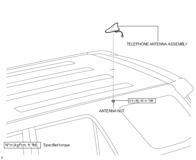
COMPONENTS
ILLUSTRATION
Removal
REMOVAL
PROCEDURE
1. DISCONNECT CABLE FROM NEGATIVE BATTERY TERMINAL
NOTICE:
When disconnecting the cable, some systems need to be initialized after the cable
is reconnected (See page .gif) ).
).
2. REMOVE ROOF HEADLINING ASSEMBLY
(a) Remove the roof headlining assembly (See page
).
3. REMOVE TELEPHONE ANTENNA ASSEMBLY
|
(a) Remove the antenna nut. |
|
|
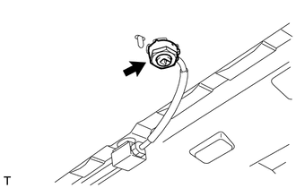
(b) Disconnect the connector. |
|
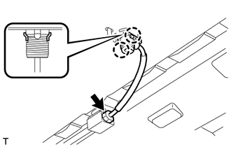
(c) Detach the 2 claws and remove the telephone antenna.
Installation
INSTALLATION
PROCEDURE
1. INSTALL TELEPHONE ANTENNA ASSEMBLY
|
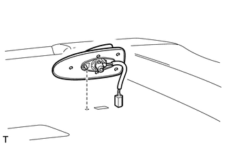
(a) Align the positioning pin of the telephone antenna with the hole and set the antenna on the vehicle. |
|
(b) Attach the 2 claws to install the telephone antenna.
(c) Connect the connector.
(d) Install the antenna nut.
Torque:
4.5 N·m {46 kgf·cm, 40 in·lbf}
2. INSTALL ROOF HEADLINING ASSEMBLY
(a) Install the roof headlining assembly (See page
.gif) ).
).
3. CONNECT CABLE TO NEGATIVE BATTERY TERMINAL
NOTICE:
When disconnecting the cable, some systems need to be initialized after the cable
is reconnected (See page ).
4. CHECK SRS WARNING LIGHT
(a) Check the SRS warning light (See page ).
 Unable To Connect To Call Center
DESCRIPTION
This may occur when the intensity of the telephone radio frequency was very weak,
PRL updates are required or the Safety Connect system has a malfunction, and a DTC
is stored.
PROCED ...
 Telephone Microphone
Components
COMPONENTS
ILLUSTRATION
ILLUSTRATION
Removal
REMOVAL
PROCEDURE
1. REMOVE DRIVE MONITOR SWITCH
2. REMOVE MAP LIGHT ASSEMBLY
3. REMOVE TELEPHONE MICROPHONE ASSEMBLY
...
Other materials about Toyota 4Runner:
Installation
INSTALLATION
PROCEDURE
1. INSTALL REAR FLOOR SIDE AIRBAG SENSOR
(a) Turn the ignition switch off.
(b) Disconnect the cable from the negative (-) battery terminal.
CAUTION:
Wait at least 90 seconds after disconnecting the cable from the negative (-)
bat ...
Air Inlet Damper Control Servo Motor Circuit (B1442)
DESCRIPTION
The recirculation damper servo sub-assembly sends pulse signals to inform the
No. 1 air conditioning amplifier assembly of the damper position. The No. 1 air
conditioning amplifier assembly activates the motor (normal or reverse) based on
th ...

0.0262