Toyota 4Runner: Rear No. 1 Seat Inner Belt Assembly(for 60/40 Split Slide Walk-in Seat Type Rh Side)
Components
COMPONENTS
ILLUSTRATION
Installation
INSTALLATION
CAUTION / NOTICE / HINT
CAUTION:
Wear protective gloves. Sharp areas on the parts may injure your hands.
HINT:
A bolt without a torque specification is shown in the standard bolt chart (See
page .gif) ).
).
PROCEDURE
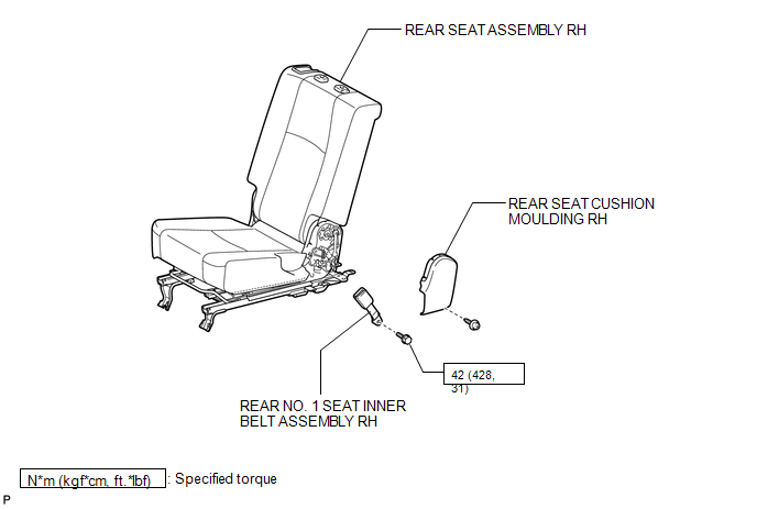
1. INSTALL REAR NO. 1 SEAT INNER BELT ASSEMBLY RH
(a) Install the inner belt with the bolt.
Torque:
42 N·m {428 kgf·cm, 31 ft·lbf}
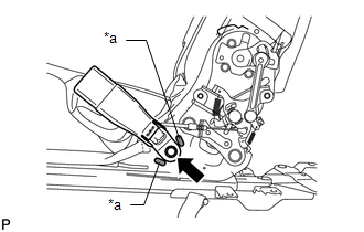
NOTICE:
Do not allow the anchor part of the front seat inner belt assembly to overlap the protruding part of the front seat adjuster.
Text in Illustration|
*a |
Protruding Part |
2. INSTALL REAR SEAT CUSHION MOULDING RH
3. INSTALL REAR SEAT ASSEMBLY RH
(a) Install the rear seat assembly RH (See page
).
Removal
REMOVAL
CAUTION / NOTICE / HINT
CAUTION:
Wear protective gloves. Sharp areas on the parts may injure your hands.
PROCEDURE
1. REMOVE REAR SEAT ASSEMBLY RH
(a) Remove the rear seat assembly (See page .gif)
).
2. REMOVE REAR SEAT CUSHION MOULDING RH
3. REMOVE REAR NO. 1 SEAT INNER BELT ASSEMBLY RH
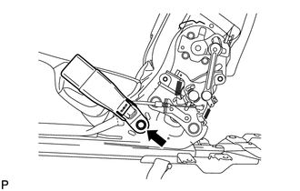
(a) Remove the bolt and inner belt.
 Removal
REMOVAL
CAUTION / NOTICE / HINT
CAUTION:
Wear protective gloves. Sharp areas on the parts may injure your hands.
PROCEDURE
1. REMOVE REAR SEAT ASSEMBLY LH
(a) Remove the rear seat assembly LH (S ...

Other materials about Toyota 4Runner:
Reverse Signal Circuit
DESCRIPTION
The radio and display receiver assembly receives a reverse signal from the park/neutral
position switch assembly.
WIRING DIAGRAM
PROCEDURE
1.
CHECK HARNESS AND CONNECTOR (REVERSE SIGNAL)
(a) Disconnect the G ...
Stereo Component Amplifier Disconnected (B15D3)
DESCRIPTION
The navigation receiver assembly and stereo component amplifier assembly are
connected by the AVC-LAN communication line.
When an AVC-LAN communication error occurs between the navigation receiver assembly
and stereo component amplifier assem ...
0.0258