Toyota 4Runner: Stereo Component Amplifier Disconnected (B15D3)
DESCRIPTION
The navigation receiver assembly and stereo component amplifier assembly are connected by the AVC-LAN communication line.
When an AVC-LAN communication error occurs between the navigation receiver assembly and stereo component amplifier assembly, this DTC will be stored.
|
DTC No. |
DTC Detection Condition |
Trouble Area |
|---|---|---|
|
B15D3 |
When either condition below is met:
|
|
HINT:
- Even if no fault is present, this DTC may be stored depending on the battery condition or engine start voltage.
- The navigation receiver assembly is the master unit.
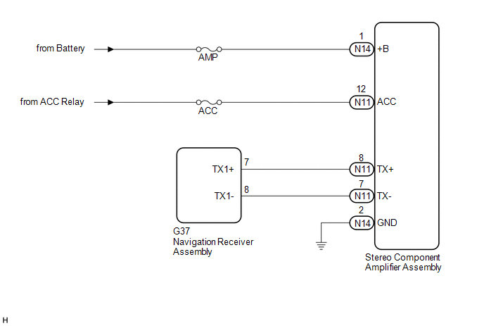
WIRING DIAGRAM
CAUTION / NOTICE / HINT
NOTICE:
- After replacing the navigation receiver assembly of vehicles subscribed to pay-type satellite radio broadcasts, registration of the XM radio ID is necessary.
- Inspect the fuses for circuits related to this system before performing the following inspection procedure.
PROCEDURE
|
1. |
CHECK DTC |
(a) If DTC B15C3 is output, perform the troubleshooting of DTC B15C3 first.
|
Result |
Proceed to |
|---|---|
|
DTC B15C3 is not output. |
A |
|
DTC B15C3 is output. |
B |
| B | .gif) |
GO TO DTC "B15C3" IN DIAGNOSTIC TROUBLE CODE CHART |
|
.gif)
|
2. |
CHECK OPTIONAL COMPONENTS (INCLUDING ASSOCIATED WIRING) |
(a) Check that optional components (including associated wiring) which generate radio waves are not installed.
|
Result |
Proceed to |
|---|---|
|
Optional components (including associated wiring) are installed. |
A |
|
Optional components (including associated wiring) are not installed. |
B |
HINT:
- Electrical noise from radio waves generated by optional components or the wiring for those components may affect AVC-LAN communication.
- This DTC may be stored when an AVC-LAN communication error occurs due to electrical noise.
| B | |
GO TO STEP 4 |
|
|
3. |
REMOVE OPTIONAL COMPONENTS (INCLUDING ASSOCIATED WIRING) |
(a) Remove optional components (including associated wiring).
NOTICE:
Do not remove optional components or associated wiring without the permission of the customer.
|
|
4. |
CHECK DTC |
(a) Clear the DTCs (See page .gif) ).
).
(b) Recheck for DTCs and check if the same DTC are output again.
OK:
No DTCs are output.
| OK | |
END |
|
|
5. |
CHECK HARNESS AND CONNECTOR (STEREO COMPONENT AMPLIFIER ASSEMBLY - BATTERY, BODY GROUND) |
(a) Disconnect the N14 and N11 stereo component amplifier assembly connectors.
(b) Measure the resistance according to the value(s) in the table below.
Standard Resistance:
|
Tester Connection |
Condition |
Specified Condition |
|---|---|---|
|
N14-2 (GND) - Body ground |
Always |
Below 1 Ω |
(c) Measure the voltage according to the value(s) in the table below.
Standard Voltage:
|
Tester Connection |
Switch Condition |
Specified Condition |
|---|---|---|
|
N14-1 (+B) - N14-2 (GND) |
Always |
11 to 14 V |
|
N11-12 (ACC) - N14-2 (GND) |
Ignition switch ACC |
11 to 14 V |
| NG | |
REPAIR OR REPLACE HARNESS OR CONNECTOR |
|
|
6. |
CHECK HARNESS AND CONNECTOR (NAVIGATION RECEIVER ASSEMBLY - STEREO COMPONENT AMPLIFIER ASSEMBLY) |
(a) Disconnect the G37 navigation receiver assembly connector.
(b) Disconnect the N11 stereo component amplifier assembly connector.
(c) Measure the resistance according to the value(s) in the table below.
Standard Resistance:
|
Tester Connection |
Condition |
Specified Condition |
|---|---|---|
|
G37-7 (TX1+) - N11-8 (TX+) |
Always |
Below 1 Ω |
|
G37-8 (TX1-) - N11-7 (TX-) |
Always |
Below 1 Ω |
|
G37-7 (TX1+) - Body ground |
Always |
10 kΩ or higher |
|
G37-8 (TX1-) - Body ground |
Always |
10 kΩ or higher |
| NG | |
REPAIR OR REPLACE HARNESS OR CONNECTOR |
|
|
7. |
REPLACE STEREO COMPONENT AMPLIFIER ASSEMBLY |
(a) Replace the stereo component amplifier assembly (See page
).
(b) Clear the DTCs (See page ).
(c) Recheck for DTCs and check if the same DTC are output again.
OK:
No DTCs are output.
| OK | |
END |
| NG | |
REPLACE NAVIGATION RECEIVER ASSEMBLY |
 Speaker Output Short (B15C3)
DESCRIPTION
This DTC is stored when a malfunction occurs in the speakers.
DTC No.
DTC Detection Condition
Trouble Area
B15C3
A short is d ...
 XM Tuner Antenna Disconnected (B15FE,B15FF)
DESCRIPTION
These DTCs are stored when a malfunction occurs in the satellite radio antenna
assembly which is connected to the stereo component tuner assembly.
DTC No.
DTC Det ...
Other materials about Toyota 4Runner:
Front Airbag Sensor LH Malfunction (B1615/14)
DESCRIPTION
The front airbag sensor LH consists of the diagnostic circuit and frontal deceleration
sensor, etc.
If the center airbag sensor receives signals from the frontal deceleration sensor,
it determines whether the SRS should be activated.
DTC B16 ...
Steering Angle Sensor Unusual Bank Angle Detected (C1440)
DESCRIPTION
If the skid control ECU determines that the vehicle is being driven at a steep
bank angle, the skid control ECU stores DTC C1440 while VSC operation is temporarily
disabled.
It is not a malfunction if the system and sensor circuits are normal ...

0.0145