Toyota 4Runner: Rear Upper Arm
Components
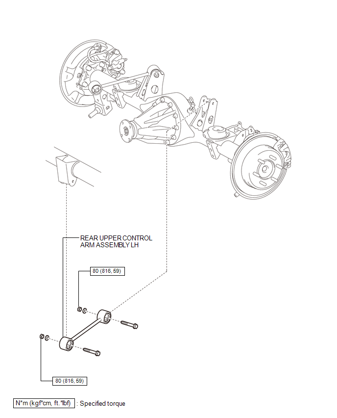
COMPONENTS
ILLUSTRATION
Removal
REMOVAL
CAUTION / NOTICE / HINT
HINT:
- Use the same procedure for the RH and LH sides.
- The procedure listed below is for the LH side.
PROCEDURE
1. REMOVE REAR WHEEL
2. REMOVE REAR UPPER CONTROL ARM ASSEMBLY LH
|
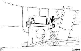
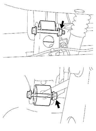
(a) Remove the nut, washer and bolt from the rear axle housing. HINT: Turn the nut while holding the bolt. |
|
|
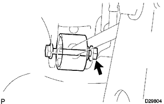
(b) Remove the nut, washer, bolt and upper control arm assembly. HINT: Turn the nut while holding the bolt. |
|
Installation
INSTALLATION
CAUTION / NOTICE / HINT
HINT:
- Use the same procedure for the RH and LH sides.
- The procedure listed below is for the LH side.
- A bolt without a torque specification is shown in the standard bolt
chart (See page
.gif) ).
).
PROCEDURE
1. TEMPORARILY INSTALL REAR UPPER CONTROL ARM ASSEMBLY LH
(a) Temporarily install the upper control arm assembly and washer with the nut and bolt.
(b) Temporarily install the upper control arm assembly and washer to the rear axle housing with the nut and bolt.
2. INSTALL REAR WHEEL
Torque:
for aluminum wheel :
103 N·m {1050 kgf·cm, 76 ft·lbf}
for steel wheel :
112 N·m {1142 kgf·cm, 83 ft·lbf}
3. STABILIZE SUSPENSION
4. TIGHTEN REAR UPPER CONTROL ARM ASSEMBLY LH
|
(a) Tighten the 2 nuts. Torque: 80 N·m {816 kgf·cm, 59 ft·lbf} HINT: Turn the nut while holding the bolt. |
|
 Rear Suspension System
Problem Symptoms Table
PROBLEM SYMPTOMS TABLE
HINT:
Use the table below to help determine the cause of problem symptoms. If multiple
suspected areas are listed, the potential causes of the symp ...

Other materials about Toyota 4Runner:
Installation
INSTALLATION
CAUTION / NOTICE / HINT
HINT:
Use the same procedure for the RH and LH sides.
The procedure listed below is for the LH side.
PROCEDURE
1. INSTALL REAR DOOR INSIDE LOCKING CABLE ASSEMBLY LH
2. INSTALL REAR DOOR LOCK REMOT ...
Manual (SOS) Switch Green Indicator Malfunction (B1571)
DESCRIPTION
This DTC is stored when the DCM (Telematics Transceiver) detects an open or short
in the manual (SOS) switch green indicator circuit of the manual (SOS) switch. The
manual (SOS) switch green indicator illuminates after the ignition switch is t ...

0.0177