Toyota 4Runner: Reassembly
REASSEMBLY
PROCEDURE
1. INSTALL FRONT OIL PUMP OIL SEAL
|
(a) Using SST and a hammer, tap in a new oil seal. SST: 09350-30020 09351-32140 HINT: Make sure the oil seal end is flush with the outer edge of the pump body. |
|
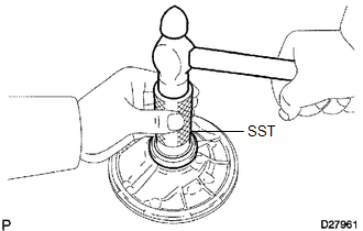
(b) Coat the lip of the oil seal with MP grease.
2. FIX FRONT OIL PUMP BODY SUB-ASSEMBLY
(a) Place the oil pump body on the torque converter clutch.
3. INSTALL FRONT OIL PUMP DRIVEN GEAR
|
(a) Coat the driven gear with ATF. |
|
.png)
(b) Install the driven gear to the oil pump body.
4. INSTALL FRONT OIL PUMP DRIVE GEAR
|
(a) Coat the drive gear with ATF. |
|
.png)
(b) Install the drive gear to the oil pump body.
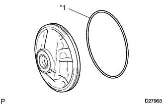
5. INSTALL FRONT OIL PUMP BODY O-RING
|
(a) Coat a new O-ring with ATF and install it to the oil pump body. Text in Illustration
|
|
6. INSTALL STATOR SHAFT ASSEMBLY
|
(a) Align the bolt holes of the stator shaft with the bolt holes of the oil pump body and install the stator shaft to the oil pump body. |
|
.png)
(b) Install the 14 bolts.
Torque:
11 N·m {110 kgf·cm, 8 ft·lbf}
7. INSTALL CLUTCH DRUM OIL SEAL RING
|
(a) Coat 3 new oil seal rings with ATF. |
|
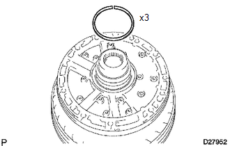
(b) Squeeze the ends of the 3 oil seal rings together with an overlap distance of 8 mm (0.314 in.) or less, and then install them to the starter shaft groove.
HINT:
After installing the oil seal rings, check that they rotate smoothly.
NOTICE:
Do not excessively widen the rings.
8. INSPECT OIL PUMP DRIVE GEAR ROTATION
.gif)
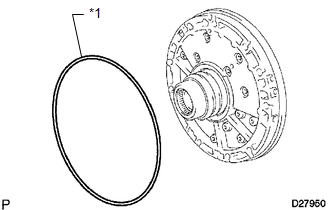
9. INSTALL AUTOMATIC TRANSMISSION CASE O-RING
|
(a) Coat a new O-ring with ATF and install it to the oil pump assembly. Text in Illustration
|
|
 Inspection
INSPECTION
PROCEDURE
1. INSPECT FRONT OIL PUMP BODY SUB-ASSEMBLY
(a) Using a dial indicator, measure the inside diameter of the oil pump
body bush.
Maximum inside diameter:
38 ...

Other materials about Toyota 4Runner:
Installation
INSTALLATION
CAUTION / NOTICE / HINT
HINT:
A bolt without a torque specification is shown in the standard bolt chart (See
page ).
PROCEDURE
1. INSTALL INSTRUMENT PANEL REINFORCEMENT ASSEMBLY
(a) Attach the 2 claws to install the instrument panel reinf ...
Air Conditioning Control Panel does not Operate
DESCRIPTION
When a switch of the air conditioning control assembly is operated, the air conditioning
control assembly uses LIN communication to communicate with the air conditioning
amplifier. If a switch of the air conditioning control assembly does not ...

0.0123