Toyota 4Runner: Removal
REMOVAL
PROCEDURE
1. PLACE FRONT WHEELS FACING STRAIGHT AHEAD
2. REMOVE FRONT WHEELS
3. REMOVE NO. 1 ENGINE UNDER COVER SUB-ASSEMBLY
Click here .gif)
4. REMOVE REAR ENGINE UNDER COVER ASSEMBLY
Click here
5. REMOVE FRONT DIFFERENTIAL CARRIER ASSEMBLY (for 4WD)
Click here
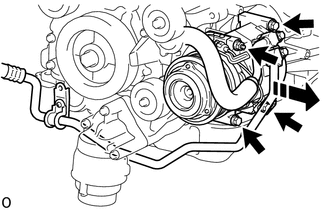
6. DISCONNECT COOLER COMPRESSOR ASSEMBLY
HINT:
This procedure is performed to make space for removing and installing the power steering link installation bolt.
(a) Remove the fan and generator V belt.
Click here
|
(b) Remove the bolt to separate the suction hose sub-assembly. |
|
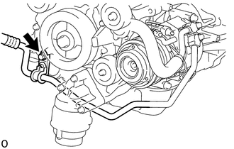
(c) Remove the 3 bolts and nut, and separate the cooler compressor assembly in the direction shown in the illustration.
 |
Separate in this Direction |
7. DISCONNECT NO. 2 STEERING INTERMEDIATE SHAFT
(a) Disconnect the No. 2 steering intermediate shaft (See page
).
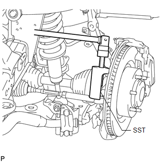
8. DISCONNECT TIE ROD END SUB-ASSEMBLY LH
|
(a) Using SST, disconnect the tie rod end assembly. SST: 09610-20012 |
|
9. DISCONNECT TIE ROD END SUB-ASSEMBLY RH
HINT:
Use the same procedures described for the LH side.
10. REMOVE TIE ROD END SUB-ASSEMBLY LH
HINT:
Only remove the tie rod end sub-assembly LH. The tie rod end sub-assembly RH does not need to be removed.
|
(a) Put matchmarks on the tie rod assembly LH, lock nut and steering rack end sub-assembly. |
|
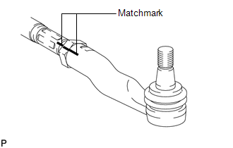
(b) Remove the tie rod assembly LH and lock nut.
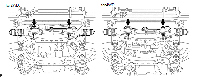
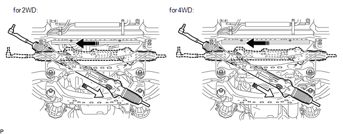
11. REMOVE RACK AND PINION POWER STEERING GEAR ASSEMBLY
(a) Remove the 2 bolts, 2 nuts and steering gear assembly.
|
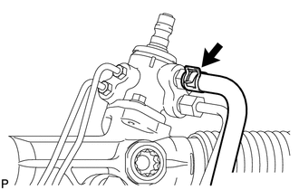
(b) Remove the clamp and disconnect the pressure feed tube (return tube side) from the steering gear. NOTICE: Do not damage the pressure feed tube. |
|
|
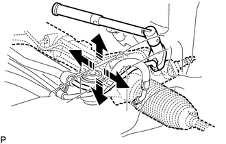
(c) Using a union nut wrench, disconnect the pressure feed tube (pressure feed tube side) from the power steering gear. NOTICE: Do not damage the pressure feed tube. HINT: Move the steering gear until it reaches a position where the pressure feed tube can be removed, and then perform the procedure. |
|
|
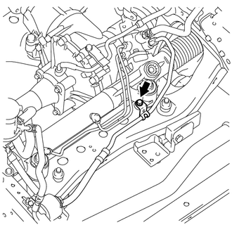
(d) Remove the bolt and disconnect the pressure feed tube clamp. NOTICE: Do not damage the pressure feed tube. |
|
(e) Pull the power steering gear assembly out of the vehicle in the order shown in the illustration.
|
|
Remove in this Direction (1) |
 |
Remove in this Direction (2) |
 Components
COMPONENTS
ILLUSTRATION
ILLUSTRATION
ILLUSTRATION
...
 Disassembly
DISASSEMBLY
CAUTION / NOTICE / HINT
NOTICE:
When using a vise, do not overtighten it.
PROCEDURE
1. REMOVE TIE ROD END SUB-ASSEMBLY LH
(a) Put matchmarks on the tie rod end LH and stee ...
Other materials about Toyota 4Runner:
Front Stabilizer Bar(w/o Kdss)
Components
COMPONENTS
ILLUSTRATION
ILLUSTRATION
Inspection
INSPECTION
PROCEDURE
1. INSPECT FRONT STABILIZER LINK ASSEMBLY LH
(a) As shown in the illustration, flip the ball joint stud back and forth
5 times.
...
Precaution
PRECAUTION
1. Kinetic Dynamic Suspension System
CAUTION:
Be sure to check the pipe connections and whether or not any hydraulic
circuit parts are damaged before performing work as the hydraulic circuits
become highly pressurized during air b ...

0.0085