Toyota 4Runner: Removal
REMOVAL
PROCEDURE
1. REMOVE UPPER RADIATOR SUPPORT SEAL
.gif)
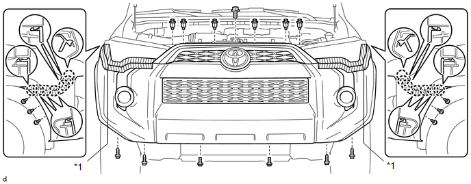
2. REMOVE FRONT BUMPER COVER
(a) Put protective tape around the front bumper cover.
(b) Remove the 3 bolts, 10 screws and 6 clips.
(c) Detach the 14 claws to remove the front bumper cover with radiator grille.
 Text in Illustration
|
*1 |
Protective Tape |
- |
- |
(d) Disconnect the 2 connectors.
3. REMOVE UPPER CENTER FRONT BUMPER RETAINER
4. REMOVE FRONT BUMPER LOWER COVER
|
(a) Remove the clip, 5 bolts and front lower bumper cover. |
|
5. REMOVE RADIATOR SIDE DEFLECTOR LH
6. REMOVE RADIATOR SIDE DEFLECTOR RH
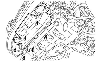
7. REMOVE FRONT BUMPER ENERGY ABSORBER
|
(a) Remove the front bumper energy absorber. |
|
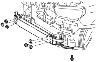
8. REMOVE FRONT BUMPER REINFORCEMENT SUB-ASSEMBLY
|
(a) Remove the 6 nuts, screw and front bumper reinforcement sub-assembly. |
|
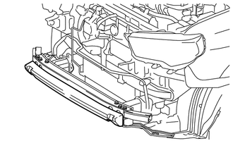
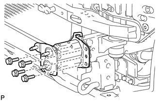
9. REMOVE NO. 2 FRONT BUMPER EXTENSION SUB-ASSEMBLY LH
|
(a) Remove the 4 bolts and No. 2 front bumper extension sub-assembly LH. |
|
10. REMOVE NO. 2 FRONT BUMPER EXTENSION SUB-ASSEMBLY RH
HINT:
Use the same procedure as for the LH side.
11. REMOVE FRONT BUMPER SIDE SUPPORT LH
|
(a) Remove the bolt and screw. |
|
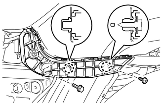
(b) Detach the 2 claws to remove the front bumper side support LH.
12. REMOVE FRONT BUMPER SIDE SUPPORT RH
HINT:
Use the same procedure as for the LH side.
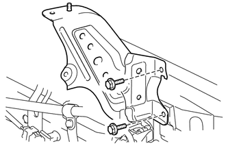
13. REMOVE FRONT BUMPER BRACKET SUB-ASSEMBLY LH
|
(a) Remove the 2 bolts and front bumper bracket sub-assembly LH. |
|
14. REMOVE FRONT BUMPER BRACKET SUB-ASSEMBLY RH
HINT:
Use the same procedure as for the LH side.
 Components
COMPONENTS
ILLUSTRATION
ILLUSTRATION
ILLUSTRATION
...
 Disassembly
DISASSEMBLY
PROCEDURE
1. REMOVE RADIATOR GRILLE
2. REMOVE FRONT BUMPER EXTENSION MOUNTING BRACKET (w/ License Plate Bracket)
(a) Remove the 2 screws to remove the front bumper extens ...
Other materials about Toyota 4Runner:
Passenger Airbag ON/OFF Indicator Circuit Malfunction (B1660/43)
DESCRIPTION
The passenger airbag ON/OFF indicator circuit consists of the airbag sensor assembly
and passenger airbag ON/OFF indicator.
The passenger airbag ON/OFF indicator indicates the operation condition of the
instrument panel passenger airbag, lowe ...
Steering Pad Switch Circuit
DESCRIPTION
This circuit sends an operation signal from the steering pad switch assembly
to the navigation receiver assembly.
If there is an open in the circuit, the audio system cannot be operated using
the steering pad switch assembly.
If there is a s ...

0.0278