Toyota 4Runner: Removal
REMOVAL
CAUTION / NOTICE / HINT
HINT:
- Use the same procedure for the RH and LH sides.
- The procedure listed below is for the LH side.
PROCEDURE
1. DISCONNECT CABLE FROM NEGATIVE BATTERY TERMINAL
CAUTION:
Wait at least 90 seconds after disconnecting the cable from the negative (-) battery terminal to disable the SRS system.
NOTICE:
When disconnecting the cable, some systems need to be initialized after the cable
is reconnected (See page .gif) ).
).
2. REMOVE REAR DOOR INSIDE HANDLE BEZEL LH
3. REMOVE REAR DOOR TRIM BOARD SUB-ASSEMBLY LH
4. REMOVE REAR DOOR INNER GLASS WEATHERSTRIP LH
5. REMOVE REAR DOOR SERVICE HOLE COVER LH
6. REMOVE REAR DOOR GLASS RUN LH
7. REMOVE REAR DOOR WINDOW DIVISION BAR SUB-ASSEMBLY LH
8. REMOVE REAR DOOR QUARTER WINDOW GLASS LH
9. REMOVE REAR DOOR GLASS SUB-ASSEMBLY LH
10. REMOVE REAR DOOR BELT MOULDING LH
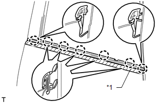
(a) Detach the 7 claws and remove the rear door belt moulding.
Text in Illustration|
*1 |
Protective Tape |
 Components
COMPONENTS
ILLUSTRATION
ILLUSTRATION
...
 Installation
INSTALLATION
CAUTION / NOTICE / HINT
HINT:
Use the same procedure for the RH and LH sides.
The procedure listed below is for the LH side.
PROCEDURE
1. INSTALL REAR DOOR BELT MOU ...
Other materials about Toyota 4Runner:
Tire inflation pressure
Tire inflation pressure
The recommended cold tire inflation pressure and tire size are displayed on
the tire and loading information label.
Inspection and adjustment procedure
1. Tire valve 2. Tire pressure gauge
Remove the tire valve cap.
Press t ...
Child restraint systems with a top tether strap
Secure the child restraint system using a seat belt or the lower anchors, and
remove the head restraint.
Open the anchor bracket cover, latch the hook onto the anchor bracket and
tighten the top tether strap.
Make sure the top tether strap is securel ...

0.0256