Toyota 4Runner: Removal
REMOVAL
PROCEDURE
1. DISCONNECT CABLE FROM NEGATIVE BATTERY TERMINAL
NOTICE:
When disconnecting the cable, some systems need to be initialized after the cable
is reconnected (See page .gif) ).
).
2. REMOVE NO. 2 DOOR INSIDE HANDLE BEZEL LH
3. REMOVE REAR DOOR TRIM BOARD SUB-ASSEMBLY LH
4. REMOVE REAR DOOR INNER GLASS WEATHERSTRIP LH
5. REMOVE REAR SPEAKER ASSEMBLY
6. REMOVE REAR DOOR SERVICE HOLE COVER LH
7. REMOVE REAR DOOR GLASS RUN LH
8. REMOVE REAR DOOR WINDOW REAR LOWER FRAME SUB-ASSEMBLY LH
9. REMOVE REAR DOOR QUARTER WINDOW GLASS LH
10. REMOVE REAR DOOR GLASS SUB-ASSEMBLY LH
11. REMOVE REAR DOOR WINDOW REGULATOR SUB-ASSEMBLY LH
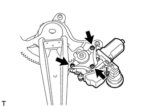
12. REMOVE POWER WINDOW REGULATOR MOTOR ASSEMBLY LH
|
(a) Using a T25 "TORX" socket wrench, remove the 3 screws and power window regulator motor. |
|
 Components
COMPONENTS
ILLUSTRATION
ILLUSTRATION
...
 Inspection
INSPECTION
PROCEDURE
1. INSPECT REAR POWER WINDOW REGULATOR MOTOR ASSEMBLY LH
(a) Check that the motor gear rotates smoothly as follows.
NOTICE:
Do not apply positive (+) battery v ...
Other materials about Toyota 4Runner:
On-vehicle Inspection
ON-VEHICLE INSPECTION
PROCEDURE
1. CHECK LOWER NO. 2 INSTRUMENT PANEL AIRBAG ASSEMBLY (VEHICLE NOT INVOLVED IN
COLLISION)
(a) Perform a diagnostic system check (See page
).
(b) With the lower No. 2 instrument panel airbag installed on the vehicle, perf ...
Open or Short in Front Speed Sensor RH Circuit (C1405,C1406)
DESCRIPTION
Refer to DTCs C1401 and C1402 (See page ).
DTC Code
DTC Detection Condition
Trouble Area
C1405
C1406
Either condition is met:
An open in the speed sensor signal circui ...

0.0257