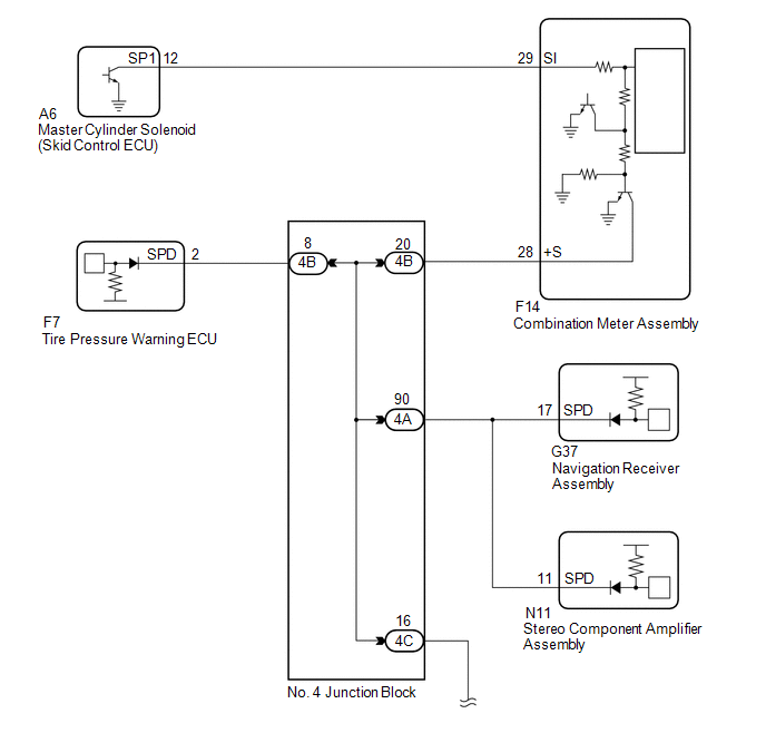
Toyota 4Runner: Vehicle Speed Signal Circuit between Stereo Component Amplifier and Combination Meter
DESCRIPTION
The stereo component amplifier assembly receives a vehicle speed signal from the combination meter assembly to control the ASL function.
HINT:
- A voltage of 12 V or 5 V is output from each ECU and then input to the combination meter assembly. The signal is changed to a pulse signal at the transistor in the combination meter assembly. Each ECU controls the respective systems based on the pulse signal.
- If a short occurs in any of the ECUs or in the wire harness connected to an ECU, all systems in the diagram below will not operate normally.
WIRING DIAGRAM
PROCEDURE
|
1. |
INSPECT COMBINATION METER ASSEMBLY (OUTPUT WAVEFORM) |
.gif)
| NG | .gif) |
GO TO METER / GAUGE SYSTEM |
|
.gif)
|
2. |
CHECK HARNESS AND CONNECTOR (STEREO COMPONENT AMPLIFIER ASSEMBLY - COMBINATION METER ASSEMBLY) |
(a) Disconnect the N11 stereo component amplifier assembly connector.
(b) Disconnect the F14 combination meter assembly connector.
(c) Measure the resistance according to the value(s) in the table below.
Standard Resistance:
|
Tester Connection |
Condition |
Specified Condition |
|---|---|---|
|
N11-11 (SPD) - F14-28 (+S) |
Always |
Below 1 Ω |
|
N11-11 (SPD) - Body ground |
Always |
10 kΩ or higher |
| OK | |
PROCEED TO NEXT SUSPECTED AREA SHOWN IN PROBLEM SYMPTOMS TABLE |
|
|
3. |
CHECK HARNESS AND CONNECTOR (STEREO COMPONENT AMPLIFIER ASSEMBLY - NO. 4 JUNCTION BLOCK) |
(a) Disconnect the N11 stereo component amplifier assembly connector.
(b) Disconnect the A4 No. 4 junction block connector.
(c) Measure the resistance according to the value(s) in the table below.
Standard Resistance:
|
Tester Connection |
Condition |
Specified Condition |
|---|---|---|
|
N11-11 (SPD) - 4A-90 |
Always |
Below 1 Ω |
|
N11-11 (SPD) - Body ground |
Always |
10 kΩ or higher |
| OK | |
REPAIR OR REPLACE HARNESS OR CONNECTOR (NO. 4 JUNCTION BLOCK) |
| NG | |
REPAIR OR REPLACE HARNESS OR CONNECTOR (STEREO COMPONENT AMPLIFIER ASSEMBLY - NO. 4 JUNCTION BLOCK) |
 AVC-LAN Circuit
DESCRIPTION
Each unit of the navigation system connected to the AVC-LAN (communication bus)
transfers the switch signals using the AVC-LAN.
If a short to +B or short to ground occurs in the AVC-LA ...
 Reverse Signal Circuit
DESCRIPTION
The navigation receiver assembly receives a reverse signal from the park/neutral
position switch assembly.
WIRING DIAGRAM
CAUTION / NOTICE / HINT
NOTICE:
After replacing t ...
Other materials about Toyota 4Runner:
System Diagram
SYSTEM DIAGRAM
Communication Table
Sender
Receiver
Signal
Line
Combination meter assembly
Main body ECU (Multiplex network body ECU)
Vehicle speed signal
CAN
...
Reassembly
REASSEMBLY
CAUTION / NOTICE / HINT
NOTICE:
When installing parts, coat the parts indicated by arrows with power steering
fluid (See page ).
PROCEDURE
1. INSTALL VANE PUMP HOUSING OIL SEAL
(a) Coat the lip of a new vane pump housing oil seal with MP gr ...

0.0298