Toyota 4Runner: Removal
REMOVAL
CAUTION / NOTICE / HINT
CAUTION:
Wear protective gloves. Sharp areas on the parts may injure your hands.
HINT:
- Use the same procedure for the RH and LH sides.
- The procedure listed below is for the LH side.
PROCEDURE
1. REMOVE FRONT SEAT ASSEMBLY
(See page .gif) )
)
2. REMOVE FRONT SEATBACK BOARD SUB-ASSEMBLY LH (w/ Climate Control Seat System)
3. REMOVE FRONT SEATBACK BOARD CLIP (w/ Climate Control Seat System)
Click here
4. REMOVE SEPARATE TYPE FRONT SEATBACK COVER WITH PAD
(a) w/o Climate Control Seat System:
|
(1) Remove the rubber band from the seat cushion spring. |
|
|
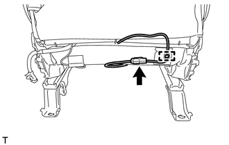
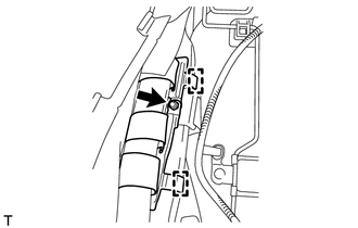
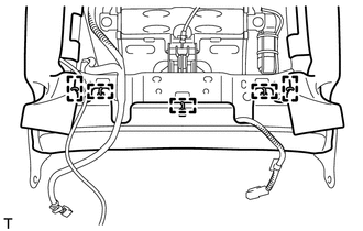
(2) Disconnect the seat heater connector and detach the seat heater wire harness clamp. |
|
|
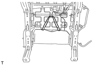
(3) Remove the 3 hog rings. |
|
(4) Open the 2 fasteners and then open the seatback cover.
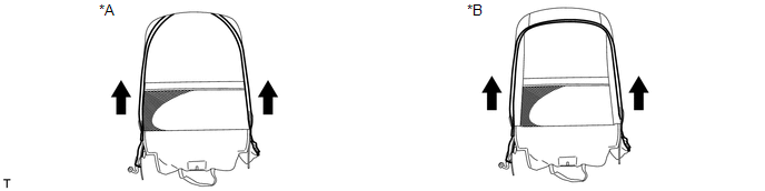 Text in Illustration
|
*A |
for Cloth Seat |
*B |
for Leather Seat |
|
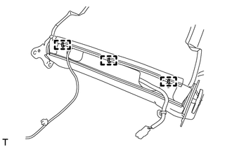
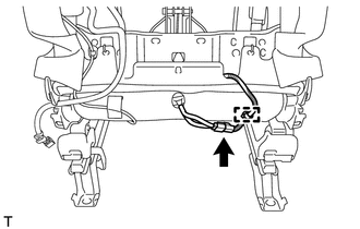
(5) Remove the nut, detach the 2 hooks and disconnect the seatback cover bracket from the separate type front seatback spring assembly. |
|
|
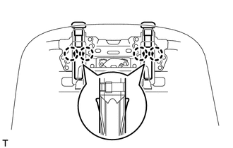
(6) Using a screwdriver, detach the 4 claws and remove the 2 headrest supports. |
|
(b) w/ Climate Control Seat System:
|
(1) Disconnect the seat heater connector and detach the seat heater wire harness clamp. |
|
|
(2) Detach the 7 hooks. |
|
|
(3) Remove the 5 hog rings. |
|
|
(4) Remove the nut, detach the 2 hooks and disconnect the seatback cover bracket from the separate type front seatback spring assembly. |
|
|
(5) Using a screwdriver, detach the 4 claws and remove the 2 headrest supports. |
|
(6) Remove the seatback cover with pad from the seatback spring.
5. REMOVE SEPARATE TYPE FRONT SEATBACK COVER
6. REMOVE FRONT SEATBACK HEATER ASSEMBLY LH
|
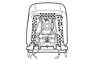
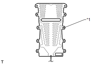
(a) Cut off the 10 tack pins which fasten the front seatback heater assembly LH to the separate type front seatback cover, and then remove the front seatback heater assembly LH from the separate type front seatback cover. Text in Illustration
|
|
 Inspection
INSPECTION
PROCEDURE
1. INSPECT FRONT SEATBACK HEATER ASSEMBLY LH
(a) Check the seatback heater.
(1) Measure the resistance according to the value(s) in the table below.
Standard Resistance:
...
 Installation
INSTALLATION
CAUTION / NOTICE / HINT
CAUTION:
Wear protective gloves. Sharp areas on the parts may injure your hands.
HINT:
Use the same procedure for the RH and LH sides.
The procedu ...
Other materials about Toyota 4Runner:
Removal
REMOVAL
CAUTION / NOTICE / HINT
PROCEDURE
1. DISCONNECT CABLE FROM NEGATIVE BATTERY TERMINAL
CAUTION:
Wait at least 90 seconds after disconnecting the cable from the negative (-)
battery terminal to disable the SRS system.
NOTICE:
When disconnecting t ...
Terminals Of Ecu
TERMINALS OF ECU
1. CHECK DRIVER SIDE JUNCTION BLOCK ASSEMBLY, MAIN BODY ECU (MULTIPLEX NETWORK
BODY ECU)
(a) Remove the main body ECU (multiplex network body ECU) (See page
).
(b) Measure the voltage and resistance according to the value(s) in the ta ...

0.0068