Toyota 4Runner: Removal
REMOVAL
PROCEDURE
1. REMOVE REAR NO. 1 FLOOR STEP COVER (w/ Rear No. 2 Seat)
.gif)
2. REMOVE QUARTER SCUFF PLATE RH (w/ Rear No. 2 Seat)
3. REMOVE REAR DOOR SCUFF PLATE RH
4. REMOVE REAR DOOR OPENING TRIM WEATHERSTRIP RH
5. REMOVE OUTER LAP BELT ANCHOR COVER
6. REMOVE NO. 1 LUGGAGE COMPARTMENT TRIM COVER (w/o Deck Board)
7. REMOVE NO. 1 DECK BOARD SUB-ASSEMBLY (w/o Deck Board)
8. REMOVE NO. 2 LUGGAGE COMPARTMENT TRIM COVER (w/ Deck Board, w/o Rear No. 2 Seat)
9. REMOVE NO. 2 DECK BOARD SUB-ASSEMBLY (w/ Deck Board)
10. REMOVE REAR NO. 2 FLOOR BOARD ASSEMBLY (w/ Deck Board)
11. REMOVE LUGGAGE COMPARTMENT SIDE COVER SUB-ASSEMBLY LH (w/ Deck Board)
12. REMOVE LUGGAGE COMPARTMENT SIDE COVER SUB-ASSEMBLY RH (w/ Deck Board)
13. REMOVE DECK BOARD ASSEMBLY (w/ Deck Board)
14. REMOVE INNER FLOOR SIDE RAIL SUB-ASSEMBLY (w/ Deck Board)
15. REMOVE REAR FLOOR MAT REAR SUPPORT PLATE
16. REMOVE REAR FLOOR CARPET ASSEMBLY (w/o Deck Board)
17. REMOVE REAR NO. 1 SEAT OUTER LAP BELT ANCHOR COVER
18. REMOVE NO. 1 LUGGAGE COMPARTMENT TRIM HOOK
19. REMOVE FRONT DECK SIDE TRIM COVER LH
20. REMOVE FRONT DECK SIDE TRIM COVER RH
21. REMOVE NO. 1 LUGGAGE COMPARTMENT TRIM COVER
22. REMOVE DECK TRIM SIDE PANEL ASSEMBLY RH
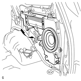
23. REMOVE NO. 1 SPEAKER ASSEMBLY WITH BOX
|
(a) Disconnect the 5 connectors. |
|
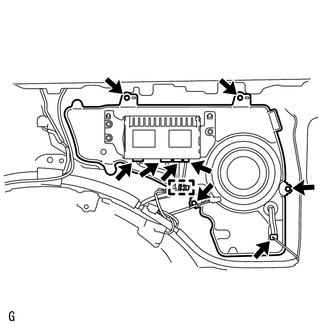
(b) Remove the 4 bolts and detach the clamp.
|
(c) While using the claws as pivot points, lift the No. 1 speaker assembly with box in the direction of the arrow in the illustration to detach the 2 claws and remove the No. 1 speaker assembly with box. |
|
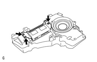
24. REMOVE STEREO COMPONENT AMPLIFIER ASSEMBLY
|
(a) Remove the 3 bolts and stereo component amplifier from the No. 1 speaker assembly with box. |
|
 Components
COMPONENTS
ILLUSTRATION
ILLUSTRATION
ILLUSTRATION
ILLUSTRATION
ILLUSTRATION
...
 Inspection
INSPECTION
PROCEDURE
1. INSPECT NO. 1 SPEAKER ASSEMBLY WITH BOX
(a) Measure the resistance according to the value(s) in the table below.
Standard Resistance:
Test ...
Other materials about Toyota 4Runner:
Confirm Cellular Phone Functionality
PROCEDURE
1.
CHECK THE CUSTOMER'S CELLULAR PHONE COMPATIBILITY
(a) Go to TIS "Bluetooth" Compatibility Portal and check if the cellular phone
is compatible.
Result
Proceed to
...
Disposal
DISPOSAL
CAUTION / NOTICE / HINT
CAUTION:
Before performing pre-disposal deployment of any SRS part, review and closely
follow all applicable environmental and hazardous material regulations. Pre-disposal
deployment may be considered hazardous material ...

0.0066