Toyota 4Runner: Removal
REMOVAL
CAUTION / NOTICE / HINT
HINT:
- Use the same procedure for the RH and LH sides.
- The procedure listed below is for the LH side.
PROCEDURE
1. REMOVE FRONT WHEEL
2. DRAIN BRAKE FLUID
NOTICE:
Wash off the brake fluid immediately if it comes into contact with a painted surface.
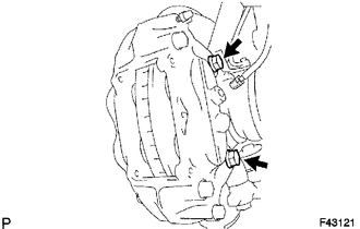
3. REMOVE FRONT DISC BRAKE PAD
|
(a) Remove the pin hold clip. Text in Illustration
NOTICE: The pin hold clip can be reused if it has sufficient rebound; no deformation or wear; and has had all rust, dirt and foreign matter cleaned off. |
|
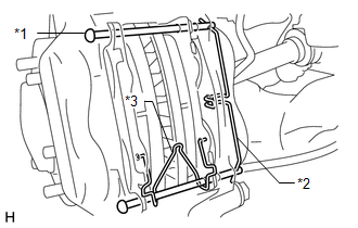
(b) Remove the 2 hole pins.
|
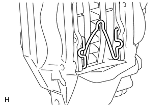
(c) Remove the front disc brake anti-rattle spring. NOTICE: The anti-rattle spring can be reused if it has sufficient rebound; no deformation, cracks or wear; and has had all rust, dirt and foreign matter cleaned off. |
|
|
(d) Remove the 2 front disc brake pads from the disc brake cylinder. |
|
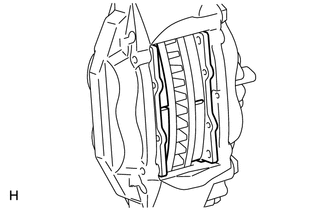
(e) Remove the front No. 1 anti-squeal shims from each pad.
4. REMOVE DISC BRAKE CYLINDER ASSEMBLY LH
|
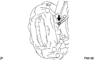
(a) Using a union nut wrench, disconnect the brake tube from the disc brake cylinder assembly. HINT: Use a container to catch brake fluid as it drains out. |
|
|
(b) Remove the 2 bolts and disc brake cylinder assembly. |
|
5. REMOVE FRONT DISC
|
(a) Place matchmarks on the disc and axle hub if planning to reuse the disc. Text in Illustration
|
|
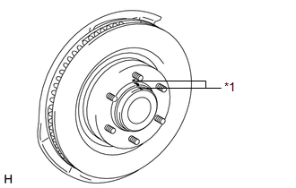
(b) Remove the front disc.
 Components
COMPONENTS
ILLUSTRATION
...
 Disassembly
DISASSEMBLY
CAUTION / NOTICE / HINT
HINT:
Use the same procedure for the RH and LH sides.
The procedure listed below is for the LH side.
PROCEDURE
1. REMOVE FRONT DISC BRAKE SET ...
Other materials about Toyota 4Runner:
Inspection
INSPECTION
PROCEDURE
1. INSPECT WINDSHIELD WIPER SWITCH ASSEMBLY
(a) Measure the resistance according to the value(s) in the table below.
Standard Resistance:
Front Wiper Switch
Tester Connection
Switch ...
Lost Communication with ECM (U0100,U0142,U0155)
DESCRIPTION
The air conditioning amplifier communicates with the ECM, main body ECU (multiplex
network body ECU) and combination meter through the CAN communication system.
DTC Code
DTC Detection Condition
Trouble Area
...

0.01