Toyota 4Runner: Removal
REMOVAL
PROCEDURE
1. DISCONNECT CABLE FROM NEGATIVE BATTERY TERMINAL
CAUTION:
Wait at least 90 seconds after disconnecting the cable from the negative (-) battery terminal to disable the SRS system.
NOTICE:
When disconnecting the cable, some systems need to be initialized after the cable
is reconnected (See page .gif) ).
).
2. REMOVE BRAKE ACTUATOR ASSEMBLY
|
(a) Release the lock lever and disconnect the brake actuator connector. NOTICE: Be careful not to allow brake fluid to enter the removed connector. |
|
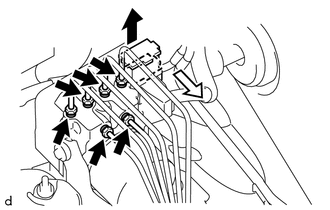
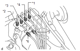
(b) Using a union nut wrench, disconnect the 6 brake lines from the brake actuator.
|
(c) Place tags or marks to identify the installation locations of each brake line. HINT:
|
|
|
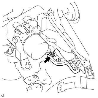
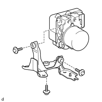
(d) Remove the nut, and disconnect the wire harness bracket from the brake actuator bracket. |
|
|
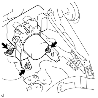
(e) Remove the 3 nuts and brake actuator with bracket from the body. NOTICE:
|
|
3. REMOVE BRAKE ACTUATOR BRACKET
|
(a) Remove the 3 bolts and brake actuator bracket from the brake actuator. NOTICE:
|
|
4. REMOVE BRAKE ACTUATOR CASE COLLAR
|
(a) Remove the 3 brake actuator case collars from the brake actuator bolt cushions. |
|
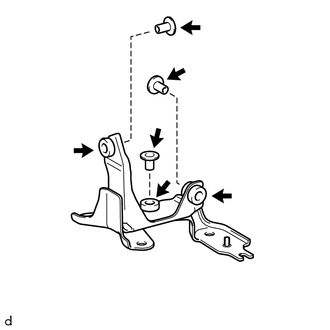
5. REMOVE BRAKE ACTUATOR BOLT CUSHION
(a) Remove the 3 brake actuator bolt cushions from the brake actuator bracket.
 On-vehicle Inspection
ON-VEHICLE INSPECTION
PROCEDURE
1. CONNECT TECHSTREAM
(a) Connect the Techstream to the DLC3.
(b) Start the engine and run it at idle.
(c) Turn the Techstream on.
(d) Enter the following menus: ...
 Installation
INSTALLATION
PROCEDURE
1. INSTALL BRAKE ACTUATOR BOLT CUSHION
(a) Install the 3 brake actuator bolt cushions to the brake actuator bracket.
2. INSTALL BRAKE ACTUATOR CASE COLLAR
(a) Install the 3 ...
Other materials about Toyota 4Runner:
Inspection
INSPECTION
PROCEDURE
1. INSPECT REAR DOOR LOCK ASSEMBLY LH
(a) Check the door lock motor operation.
(1) Apply battery voltage to the door lock motor and check the operation
of the door lock motor.
OK:
Measurement Cond ...
Terminals Of Ecu
TERMINALS OF ECU
1. TERMINALS OF ECU
Text in Illustration
*a
Component without harness connected
(Skid Control ECU)
-
-
Terminal No. (Symbol)
Terminal Description
...

0.0072