Toyota 4Runner: Short to Battery in Hall Effect Sensor Power Circuit (32)
DESCRIPTION
When there is a short to battery in the side auto step motor hall sensor power circuit, the side auto step controller ECU assembly will not operate the automatic running board.
|
DTC No. |
Detection Condition |
Trouble Area |
|---|---|---|
|
32 |
The side auto step motor hall sensor voltage is more than 4 V when the automatic running board is not in operation. |
|
WIRING DIAGRAM
.png)
PROCEDURE
|
1. |
CHECK HARNESS AND CONNECTOR (SIDE AUTO STEP MOTOR POWER SOURCE) |
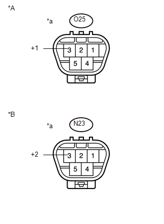
(a) Disconnect the O25*1 and N23*2 side auto step motor assembly connector.
- *1: for LH
- *2: for RH
|
(b) Measure the voltage according to the value(s) in the table below. Standard Voltage: for LH
for RH
|
|
| OK | .gif) |
REPLACE SIDE AUTO STEP MOTOR ASSEMBLY |
|
.gif)
|
2. |
CHECK HARNESS AND CONNECTOR (SIDE AUTO STEP MOTOR - SIDE AUTO STEP CONTROLLER ECU) |
(a) Disconnect the A41 side auto step controller ECU assembly connector.
(b) Measure the voltage according to the value(s) in the table below.
Standard Voltage:
|
Tester Connection |
Condition |
Specified Condition |
|---|---|---|
|
A41-14 (SSR+) - Body Ground |
Always |
Below 4 V |
| OK | |
REPLACE SIDE AUTO STEP CONTROLLER ECU ASSEMBLY |
| NG | |
REPAIR OR REPLACE HARNESS OR CONNECTOR |
 Hall Effect Sensor LH Pulse (41,42)
DESCRIPTION
When there is noise present in the side auto step motor hall pulse signal, the
side auto step controller ECU assembly halts the operation of the automatic running
board.
D ...
 Short to Battery in Motor RH Circuit (25,26)
DESCRIPTION
When there is a short to battery in the side auto step motor circuit, the side
auto step controller ECU assembly will not operate the automatic running board.
DTC No.
...
Other materials about Toyota 4Runner:
Front Passenger Side Power Window Switch
Components
COMPONENTS
ILLUSTRATION
Inspection
INSPECTION
PROCEDURE
1. INSPECT POWER WINDOW REGULATOR SWITCH ASSEMBLY
(a) Measure the resistance according to the value(s) in the table below.
Standard Resistance:
T ...
Automatic running boards
The Automatic running boards are linked to the side door operations,
extending and retracting when a side door is opened and closed. When a door is
opened or closed, the board on the same side extends or retracts.
1. Opening a door: The appropriate boar ...

0.0252