Toyota 4Runner: Speaker Output Short (B15C3)
DESCRIPTION
This DTC is stored when a malfunction occurs in the speakers.
|
DTC No. |
DTC Detection Condition |
Trouble Area |
|---|---|---|
|
B15C3 |
A short is detected in the speaker output circuit. |
|
- *1: w/ Manual (SOS) Switch
- *2: for 9 Speakers
- *3: for 8 Speakers
WIRING DIAGRAM
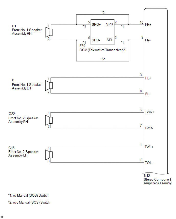
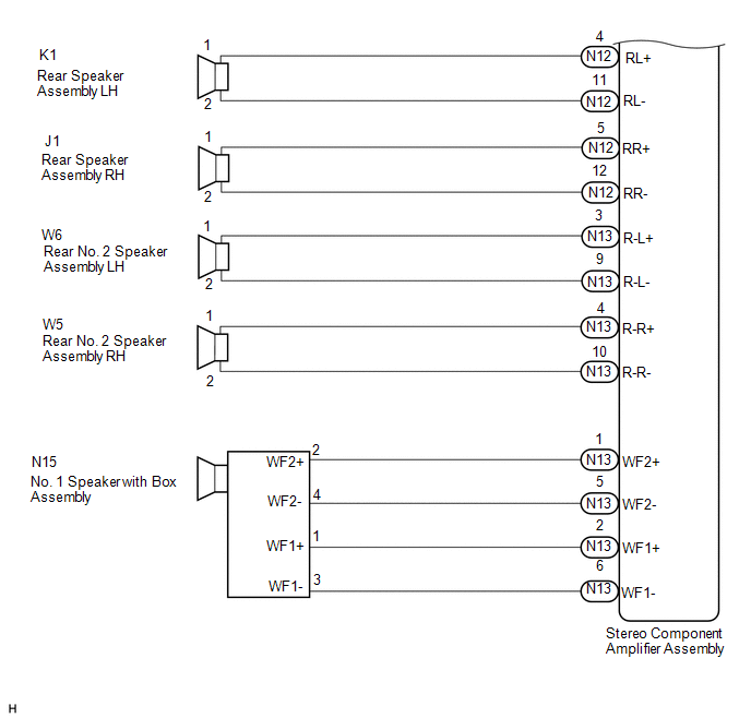
1. for 9 Speakers
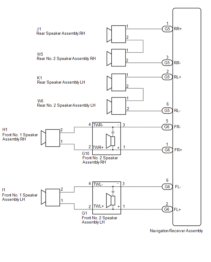
2. for 8 Speakers
PROCEDURE
|
1. |
CHECK HARNESS AND CONNECTOR |
(a) for 9 Speakers
(1) Disconnect the N12 and N13 stereo component amplifier assembly connectors, F39 DCM (telematics transceiver)*1 connector and speaker assembly connectors.
- *1: w/ Manual (SOS) Switch
(2) Measure the resistance between the stereo component amplifier assembly and body ground to check for a short circuit in the wire harness.
Standard Resistance:
|
Tester Connection |
Condition |
Specified Condition |
|---|---|---|
|
N12-10 (FR+) - Body ground |
Always |
10 kΩ or higher |
|
N12-9 (FR-) - Body ground |
Always |
10 kΩ or higher |
|
N12-3 (FL+) - Body ground |
Always |
10 kΩ or higher |
|
N12-8 (FL-) - Body ground |
Always |
10 kΩ or higher |
|
N12-2 (TWR+) - Body ground |
Always |
10 kΩ or higher |
|
N12-7 (TWR-) - Body ground |
Always |
10 kΩ or higher |
|
N12-1 (TWL+) - Body ground |
Always |
10 kΩ or higher |
|
N12-6 (TWL-) - Body ground |
Always |
10 kΩ or higher |
|
N12-4 (RL+) - Body ground |
Always |
10 kΩ or higher |
|
N12-11 (RL-) - Body ground |
Always |
10 kΩ or higher |
|
N12-5 (RR+) - Body ground |
Always |
10 kΩ or higher |
|
N12-12 (RR-) - Body ground |
Always |
10 kΩ or higher |
|
N13-3 (R-L+) - Body ground |
Always |
10 kΩ or higher |
|
N13-9 (R-L-) - Body ground |
Always |
10 kΩ or higher |
|
N13-4 (R-R+) - Body ground |
Always |
10 kΩ or higher |
|
N13-10 (R-R-) - Body ground |
Always |
10 kΩ or higher |
|
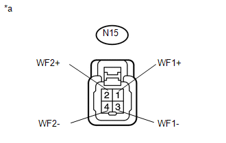
N13-1 (WF2+) - Body ground |
Always |
10 kΩ or higher |
|
N13-5 (WF2-) - Body ground |
Always |
10 kΩ or higher |
|
N13-2 (WF1+) - Body ground |
Always |
10 kΩ or higher |
|
N13-6 (WF1-) - Body ground |
Always |
10 kΩ or higher |
(3) w/ Manual (SOS) Switch
Measure the resistance between the DCM (telematics transceiver) and body ground to check for a short circuit in the wire harness.
Standard Resistance:
|
Tester Connection |
Condition |
Specified Condition |
|---|---|---|
|
F39-5 (SPO+) - Body ground |
Always |
10 kΩ or higher |
|
F39-6 (SPO-) - Body ground |
Always |
10 kΩ or higher |
(b) for 8 speakers
(1) Disconnect the G5 and G6 navigation receiver assembly connectors and speaker assembly connectors.
(2) Measure the resistance between the navigation receiver assembly, speaker assembly and body ground to check for a short circuit in the wire harness.
Standard Resistance:
|
Tester Connection |
Condition |
Specified Condition |
|---|---|---|
|
G6-1 (FR+) - Body ground |
Always |
10 kΩ or higher |
|
G6-5 (FR-) - Body ground |
Always |
10 kΩ or higher |
|
G6-2 (FL+) - Body ground |
Always |
10 kΩ or higher |
|
G6-6 (FL-) - Body ground |
Always |
10 kΩ or higher |
|
G5-1 (RR+) - Body ground |
Always |
10 kΩ or higher |
|
G5-3 (RR-) - Body ground |
Always |
10 kΩ or higher |
|
G5-2 (RL+) - Body ground |
Always |
10 kΩ or higher |
|
G5-6 (RL-) - Body ground |
Always |
10 kΩ or higher |
|
G10-2 (TWR+) - Body ground |
Always |
10 kΩ or higher |
|
G10-4 (TWR-) - Body ground |
Always |
10 kΩ or higher |
|
G1-2 (TWL+) - Body ground |
Always |
10 kΩ or higher |
|
G1-4 (TWR-) - Body ground |
Always |
10 kΩ or higher |
|
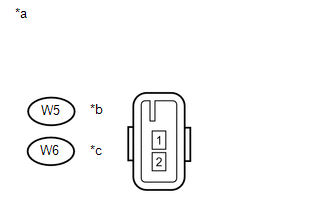
W6-1 - Body ground |
Always |
10 kΩ or higher |
|
W5-1 - Body ground |
Always |
10 kΩ or higher |
| NG | .gif) |
REPAIR OR REPLACE HARNESS OR CONNECTOR |
|
.gif)
|
2. |
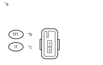
INSPECT FRONT NO. 1 SPEAKER ASSEMBLY |
|
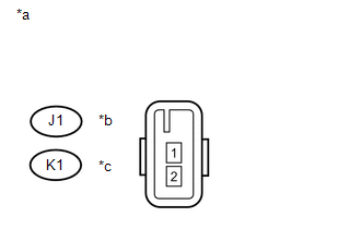
(a) Measure the resistance according to the value(s) in the table below. Standard Resistance (for 9 Speakers):
Standard Resistance (for 8 Speakers):
|
|
| NG | |
REPLACE FRONT NO. 1 SPEAKER ASSEMBLY |
|
|
3. |
REPLACE FRONT NO. 2 SPEAKER ASSEMBLY |
(a) Replace the front No. 2 speaker assembly (See page
.gif) ).
).
(b) Clear the DTCs (See page ).
(c) Recheck for DTCs and check if the same DTC are output again (See page
).
Standard:
NO DTCs are output.
HINT:
- Connect all the connectors to the front No. 2 speaker assemblies.
- If there is a possibility that either the right or left front speaker is defective, inspect by interchanging the right one with the left one.
- Perform the above inspection on both LH and RH sides.
| OK | |
END |
|
|
4. |
CONFIRM MODEL |
(a) Choose the model to be inspected.
|
Model |
Proceed to |
|---|---|
|
for 9 Speakers |
A |
|
for 8 Speakers |
B |
| B | |
GO TO STEP 7 |
|
|
5. |
REPLACE REAR SPEAKER ASSEMBLY (for 9 Speakers) |
(a) Replace the rear speaker assembly and check if the same DTC are output again.
(1) Replace the rear speaker assembly (See page
).
(2) Clear the DTCs (See page ).
(3) Recheck for DTCs and check if the same DTC are output again (See page
).
Standard:
NO DTCs are output.
HINT:
- Connect all the connectors to the rear speaker assemblies.
- If there is a possibility that either the right or left front speaker is defective, inspect by interchanging the right one with the left one.
- Perform the above inspection on both LH and RH sides.
| OK | |
END |
|
|
6. |
REPLACE REAR NO. 2 SPEAKER ASSEMBLY (for 9 Speakers) |
(a) Replace the rear No. 2 speaker assembly and check if the same DTC are output again.
(1) Replace the rear No. 2 speaker assembly (See page
).
(2) Clear the DTCs (See page ).
(3) Recheck for DTCs and check if the same DTC are output again (See page
).
Standard:
NO DTCs are output.
HINT:
- Connect all the connectors to the rear No. 2 speaker assemblies.
- If there is a possibility that either the right or left rear speaker is defective, inspect by interchanging the right one with the left one.
- Perform the above inspection on both LH and RH sides.
| OK | |
END |
| NG | |
GO TO STEP 9 |
|
7. |
INSPECT REAR SPEAKER ASSEMBLY (for 8 Speakers) |
|
(a) Measure the resistance according to the value(s) in the table below. Standard Resistance:
|
|
| NG | |
REPLACE REAR SPEAKER ASSEMBLY |
|
|
8. |
INSPECT REAR NO. 2 SPEAKER ASSEMBLY (for 8 Speakers) |
|
(a) Measure the resistance according to the value(s) in the table below. Standard Resistance:
|
|
| OK | |
REPLACE NAVIGATION RECEIVER ASSEMBLY |
| NG | |
REPLACE REAR NO.2 SPEAKER ASSEMBLY |
|
9. |
INSPECT NO. 1 SPEAKER WITH BOX ASSEMBLY |
|
(a) Measure the resistance according to the value(s) in the table below. Standard Resistance:
|
|
|
Condition |
Proceed to |
|---|---|
|
OK (w/ Manual (SOS) Switch) |
A |
|
OK (w/o Manual (SOS) Switch) |
B |
|
NG |
C |
| B | |
REPLACE STEREO COMPONENT AMPLIFIER ASSEMBLY |
| C | |
REPLACE NO. 1 SPEAKER WITH BOX ASSEMBLY |
|
|
10. |
INSPECT DCM (TELEMATICS TRANSCEIVER) |
(a) Disconnect the F39 DCM (Telematics transceiver) connector.
|
(b) Measure the resistance according to the value(s) in the table below. Standard Resistance:
|
|

| OK | |
REPLACE STEREO COMPONENT AMPLIFIER ASSEMBLY |
| NG | |
REPLACE DCM (TELEMATICS TRANSCEIVER) |
 Speed Signal Malfunction (B15C2)
DESCRIPTION
The navigation receiver assembly receives a vehicle speed signal from the combination
meter assembly and information from the navigation antenna assembly, and then adjusts
the vehicle ...
 Stereo Component Amplifier Disconnected (B15D3)
DESCRIPTION
The navigation receiver assembly and stereo component amplifier assembly are
connected by the AVC-LAN communication line.
When an AVC-LAN communication error occurs between the navigat ...
Other materials about Toyota 4Runner:
Removal
REMOVAL
CAUTION / NOTICE / HINT
HINT:
Use the same procedure for both the RH and LH sides.
The procedure listed below is for the LH side.
PROCEDURE
1. REMOVE UPPER RADIATOR SUPPORT SEAL
2. REMOVE FRONT FENDER MAIN SEAL LH
3. REMO ...
Data List / Active Test
DATA LIST / ACTIVE TEST
1. READ DATA LIST
HINT:
Using the Techstream to read the Data List allows the values or states of switches,
sensors, actuators and other items to be read without removing any parts. This non-intrusive
inspection can be very usefu ...

0.0269