Toyota 4Runner: Terminals Of Ecu
TERMINALS OF ECU
HINT:
Operating the ignition switch, any switches or any doors triggers related ECU and sensor communication with the CAN, which causes resistance variation.
1. DISCONNECT CABLE FROM NEGATIVE BATTERY TERMINAL
(a) Disconnect the cable from the negative (-) battery terminal before measuring the resistances of the main wire and branch wire.
CAUTION:
Wait at least 90 seconds after disconnecting the cable from the negative (-) battery terminal to disable the SRS system.
NOTICE:
- Before measuring the resistance, leave the vehicle for at least a minute and do not operate the ignition switch, any switches or any doors. If doors need to be opened in order to check connectors, open the doors and leave them open.
- When disconnecting the cable some systems need to be initialized after
the cable is reconnected (See page
.gif) ).
).
2. JUNCTION CONNECTOR
(a) NO. 1 JUNCTION CONNECTOR (for 4WD)
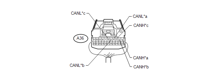 Text in Illustration
|
*a |
for Skid Control ECU (Master Cylinder Solenoid) |
*b |
for No. 2 Junction Connector |
|
*c |
for Combination Meter Assembly |
- |
- |
|
No. 1 Junction Connector |
Wiring Color |
Connect to |
|---|---|---|
|
A36-1 (CANH) |
B |
Skid control ECU (master cylinder solenoid) |
|
A36-4 (CANL) |
W |
|
|
A36-2 (CANH) |
GR |
No. 2 junction connector |
|
A36-5 (CANL) |
W |
|
|
A36-3 (CANH) |
L |
Combination meter assembly |
|
A36-6 (CANL) |
W |
(b) NO. 2 JUNCTION CONNECTOR
(1) V1 bus:
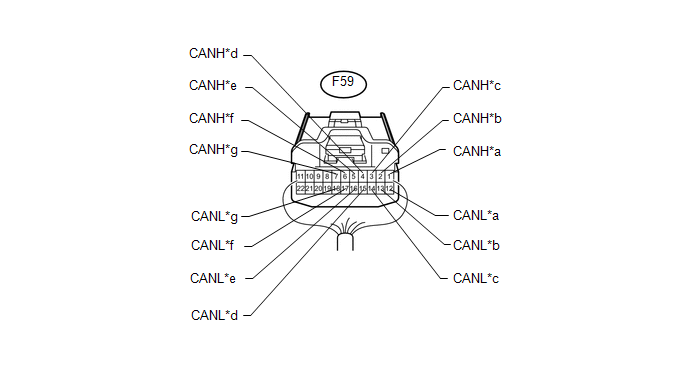 Text in Illustration
|
*a |
for No. 4 Junction Connector |
*b |
for Main Body ECU (Multiplex Network Body ECU) |
|
*c |
for Combination Meter Assembly (for 2WD) for No. 1 Junction Connector (for 4WD) |
*d |
for DLC3 |
|
*e |
for Airbag Sensor Assembly |
*f |
for Stabilizer Control ECU (w/ Kinetic Dynamic Suspension System) |
|
*g |
for Steering Angle Sensor (Spiral Cable Sub-assembly) |
- |
- |
|
No. 2 Junction Connector |
Wiring Color |
Connect to |
|---|---|---|
|
F59-1 (CANH) |
SB |
No. 4 junction connector |
|
F59-12 (CANL) |
W |
|
|
F59-2 (CANH) |
R |
Main body ECU (multiplex network body ECU) |
|
F59-13 (CANL) |
W |
|
|
F59-3 (CANH) |
L*1 GR*2 |
Combination meter assembly*1 No. 1 junction connector*2 |
|
F59-14 (CANL) |
W |
|
|
F59-4 (CANH) |
V |
DLC3 |
|
F59-15 (CANL) |
W |
|
|
F59-5 (CANH) |
Y |
Airbag sensor assembly |
|
F59-16 (CANL) |
W |
|
|
F59-6 (CANH) |
P |
Stabilizer control ECU*3 |
|
F59-17 (CANL) |
W |
|
|
F59-7 (CANH) |
G |
Steering angle sensor (spiral cable sub-assembly) |
|
F59-18 (CANL) |
W |
- *1: for 2WD
- *2: for 4WD
- *3: w/ Kinetic Dynamic Suspension System
(2) MS bus (w/ Seat Position Memory):
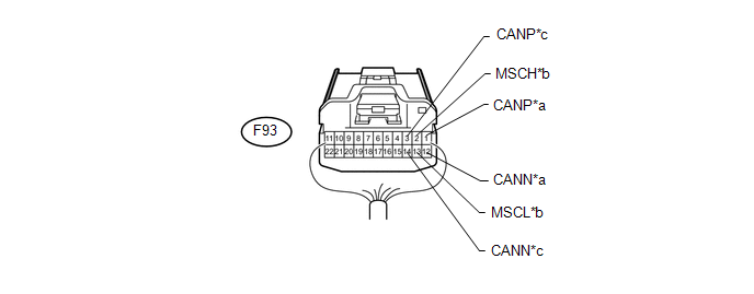 Text in Illustration
|
*a |
for Main Body ECU (Multiplex Network Body ECU) |
*b |
for Combination Meter Assembly |
|
*c |
for Front Power Seat Switch LH |
- |
- |
|
No. 2 Junction Connector |
Wiring Color |
Connect to |
|---|---|---|
|
F93-1 (CANP) |
B |
Main body ECU (multiplex network body ECU) |
|
F93-12 (CANN) |
W |
|
|
F93-2 (MSCH) |
LG |
Combination meter assembly |
|
F93-13 (MSCL) |
W |
|
|
F93-3 (CANP) |
L |
Front power seat switch LH |
|
F93-14 (CANN) |
W |
(c) NO. 3 JUNCTION CONNECTOR
(1) V1 bus:
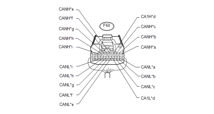 Text in Illustration
|
*a |
for No. 4 Junction Connector |
*b |
for ECM |
|
*c |
for Four Wheel Drive Control ECU (for 4WD) |
*d |
for Power Management Control ECU (w/ Smart Key System) |
|
*e |
for Power Steering ECU Assembly |
*f |
for Certification ECU (Smart Key ECU Assembly) (w/ Smart Key System) |
|
*g |
for Yaw Rate Sensor Assembly |
*h |
for Air Conditioning Amplifier Assembly (w/o Smart Key System) |
|
*i |
for Skid Control ECU (Brake Actuator Assembly) (for 2WD) |
- |
- |
|
No. 3 Junction Connector |
Wiring Color |
Connect to |
|---|---|---|
|
F60-1 (CANH) |
GR |
No. 4 junction connector |
|
F60-12 (CANL) |
W |
|
|
F60-2 (CANH) |
V |
ECM |
|
F60-13 (CANL) |
W |
|
|
F60-3 (CANH) |
G |
Four wheel drive control ECU*1 |
|
F60-14 (CANL) |
W |
|
|
F60-4 (CA1H) |
P |
Power management control ECU*2 |
|
F60-15 (CA1L) |
W |
|
|
F60-5 (CANH) |
L |
Power steering ECU assembly |
|
F60-16 (CANL) |
W |
|
|
F60-6 (CANH) |
Y |
Certification ECU (smart key ECU assembly)*2 |
|
F60-17 (CANL) |
W |
|
|
F60-7 (CANH) |
R |
Yaw rate sensor assembly |
|
F60-18 (CANL) |
W |
|
|
F60-8 (CANH) |
B |
Air conditioning amplifier assembly*3 |
|
F60-19 (CANL) |
W |
|
|
F60-9 (CANH) |
LG |
Skid control ECU (brake actuator assembly)*4 |
|
F60-20 (CANL) |
W |
- *1: for 4WD
- *2: w/ Smart Key System
- *3: w/o Smart Key System
- *4: for 2WD
(2) Power management bus (w/ Smart Key System):
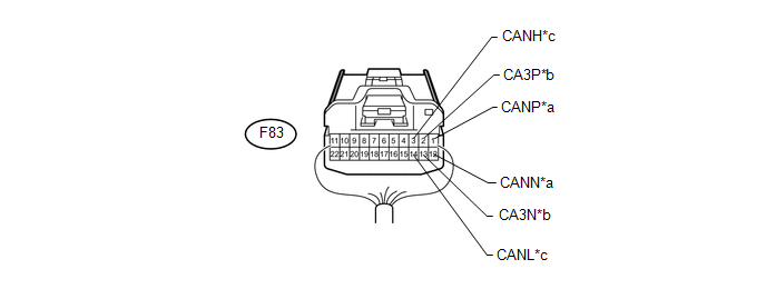 Text in Illustration
|
*a |
for ECM |
*b |
for Power Management Control ECU |
|
*c |
for Air Conditioning Amplifier Assembly |
- |
- |
|
No. 3 Junction Connector |
Wiring Color |
Connect to |
|---|---|---|
|
F83-1 (CANP) |
R |
ECM |
|
F83-12 (CANN) |
W |
|
|
F83-2 (CA3P) |
L |
Power management control ECU |
|
F83-13 (CA3N) |
W |
|
|
F83-3 (CANH) |
B |
Air conditioning amplifier assembly |
|
F83-14 (CANL) |
W |
(d) NO. 4 JUNCTION CONNECTOR
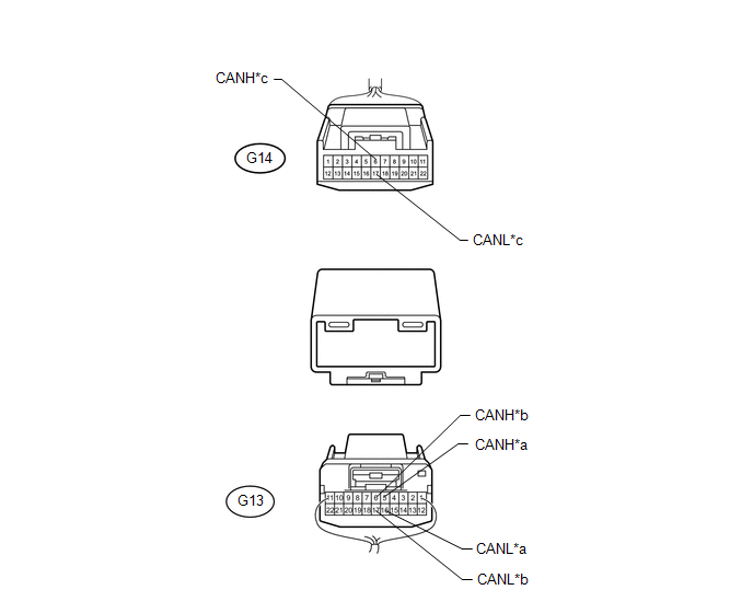 Text in Illustration
|
*a |
for No. 3 Junction Connector |
*b |
for No. 2 Junction Connector |
|
*c |
for Navigation Receiver Assembly (for Navigation Receiver Type) or Radio and Display Receiver Assembly (for Radio and Display Receiver Type) |
- |
- |
|
No. 4 Junction Connector |
Wiring Color |
Connect to |
|---|---|---|
|
G13-5 (CANH) |
GR |
No. 3 junction connector |
|
G13-16 (CANL) |
W |
|
|
G13-6 (CANH) |
SB |
No. 2 junction connector |
|
G13-17 (CANL) |
W |
|
|
G14-6 (CANH) |
P |
Navigation receiver assembly*1 Radio and display receiver assembly*2 |
|
G14-17 (CANL) |
W |
- *1: for Navigation Receiver Type
- *2: for Radio and Display Receiver Type
3. CHECK DLC3
(a) Disconnect the cable from the negative (-) battery terminal before measuring the resistances of the main wire and branch wire.
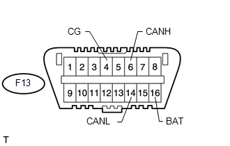
CAUTION:
Wait at least 90 seconds after disconnecting the cable from the negative (-) battery terminal to disable the SRS system.
NOTICE:
When disconnecting the cable, some systems need to be initialized after the cable
is reconnected (See page ).
(b) Measure the resistance according to the value(s) in the table below.
|
Terminal No. (Symbol) |
Wiring Color |
Switch Condition |
Specified Condition |
|---|---|---|---|
|
F13-6 (CANH) - F13-14 (CANL) |
V - W |
Ignition switch off |
54 to 69 Ω |
|
F13-6 (CANH) - F13-4 (CG) |
V - W-B |
Ignition switch off |
200 Ω or higher |
|
F13-14 (CANL) - F13-4 (CG) |
W - W-B |
Ignition switch off |
200 Ω or higher |
|
F13-6 (CANH) - F13-16 (BAT) |
V - GR |
Ignition switch off |
6 kΩ or higher |
|
F13-14 (CANL) - F13-16 (BAT) |
W - GR |
Ignition switch off |
6 kΩ or higher |
4. CHECK ECM
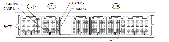 Text in Illustration
|
*a |
for V1 Bus |
*b |
for Power Management Bus (w/ Smart Key System) |
(a) Disconnect the B38, F50 and F51 ECM connectors.
(b) Measure the resistance according to the value(s) in the table below.
for V1 Bus|
Terminal No. (Symbol) |
Wiring Color |
Switch Condition |
Specified Condition |
|---|---|---|---|
|
F50-32 (CANH) - F50-31 (CANL) |
V - W |
Ignition switch off |
108 to 132 Ω |
|
F50-32 (CANH) - B38-12 (E1) |
V - BR |
Ignition switch off |
200 Ω or higher |
|
F50-31 (CANL) - B38-12 (E1) |
W - BR |
Ignition switch off |
200 Ω or higher |
|
F50-32 (CANH) - F51-24 (BATT) |
V - L |
Ignition switch off |
6 kΩ or higher |
|
F50-31 (CANL) - F51-24 (BATT) |
W - L |
Ignition switch off |
6 kΩ or higher |
|
Terminal No. (Symbol) |
Wiring Color |
Switch Condition |
Specified Condition |
|---|---|---|---|
|
F50-34 (CANP) - F50-33 (CANN) |
R - W |
Ignition switch off |
108 to 132 Ω |
|
F50-34 (CANP) - B38-12 (E1) |
R - BR |
Ignition switch off |
200 Ω or higher |
|
F50-33 (CANN) - B38-12 (E1) |
W - BR |
Ignition switch off |
200 Ω or higher |
|
F50-34 (CANP) - F51-24 (BATT) |
R - L |
Ignition switch off |
6 kΩ or higher |
|
F50-33 (CANN) - F51-24 (BATT) |
W - L |
Ignition switch off |
6 kΩ or higher |
5. CHECK DRIVER SIDE JUNCTION BLOCK ASSEMBLY, MAIN BODY ECU (MULTIPLEX NETWORK BODY ECU)
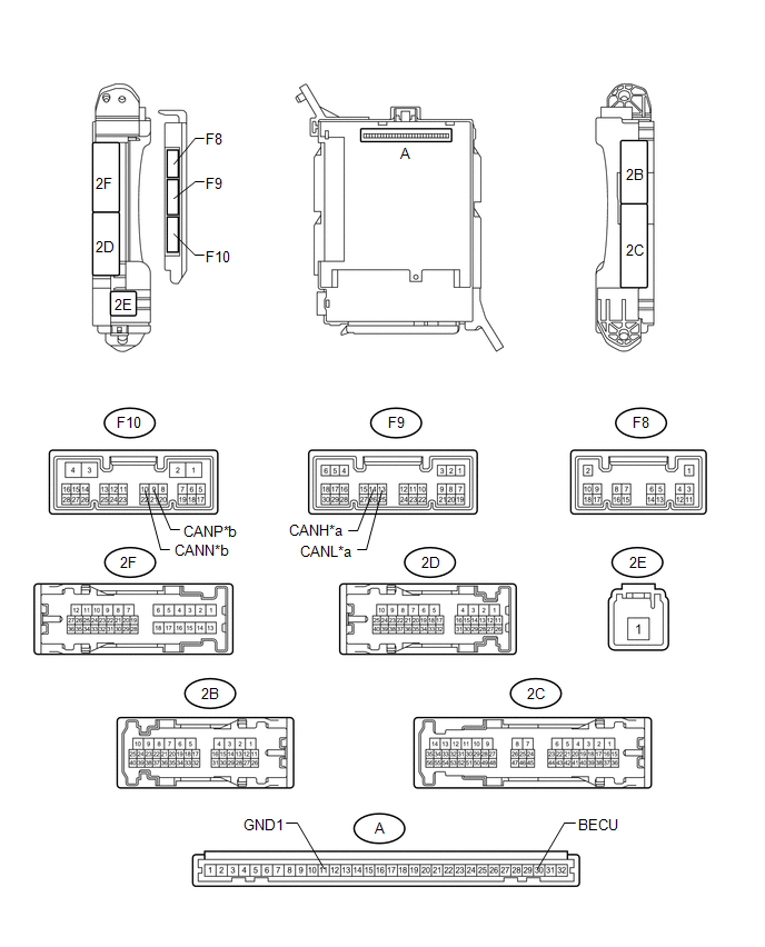 Text in Illustration
|
*a |
for V1 Bus |
*b |
for MS Bus (w/ CRAWL Control or w/ Seat Position Memory) |
(a) Remove the main body ECU (multiplex network body ECU) (See page
).
(b) Measure the resistance according to the value(s) in the table below.
for V1 Bus|
Terminal No. (Symbol) |
Wiring Color |
Switch Condition |
Specified Condition |
|---|---|---|---|
|
F9-14 (CANH) - F9-13 (CANL) |
R - W |
Ignition switch off |
54 to 69 Ω |
|
F9-14 (CANH) - A-11 (GND1) |
R - None |
Ignition switch off |
200 Ω or higher |
|
F9-13 (CANL) - A-11 (GND1) |
W - None |
Ignition switch off |
200 Ω or higher |
|
F9-14 (CANH) - A-30 (BECU) |
R - None |
Ignition switch off |
6 kΩ or higher |
|
F9-13 (CANL) - A-30 (BECU) |
W - None |
Ignition switch off |
6 kΩ or higher |
|
Terminal No. (Symbol) |
Wiring Color |
Switch Condition |
Specified Condition |
|---|---|---|---|
|
F10-9 (CANP) - F10-10 (CANN) |
B - W |
Ignition switch off |
108 to 132 Ω |
|
F10-9 (CANP) - A-11 (GND1) |
B - None |
Ignition switch off |
200 Ω or higher |
|
F10-10 (CANN) - A-11 (GND1) |
W - None |
Ignition switch off |
200 Ω or higher |
|
F10-9 (CANP) - A-30 (BECU) |
B - None |
Ignition switch off |
6 kΩ or higher |
|
F10-10 (CANN) - A-30 (BECU) |
W - None |
Ignition switch off |
6 kΩ or higher |
6. CHECK SKID CONTROL ECU (BRAKE ACTUATOR ASSEMBLY) (for 2WD)
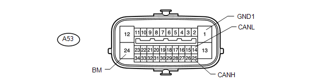
(a) Disconnect the A53 skid control ECU (brake actuator assembly) connector.
(b) Measure the resistance according to the value(s) in the table below.
|
Terminal No. (Symbol) |
Wiring Color |
Switch Condition |
Specified Condition |
|---|---|---|---|
|
A53-25 (CANH) - A53-14 (CANL) |
LG - W |
Ignition switch off |
54 to 69 Ω |
|
A53-25 (CANH) - A53-1 (GND1) |
LG - W-B |
Ignition switch off |
200 Ω or higher |
|
A53-14 (CANL) - A53-1 (GND1) |
W - W-B |
Ignition switch off |
200 Ω or higher |
|
A53-25 (CANH) - A53-24 (BM) |
LG - B |
Ignition switch off |
6 kΩ or higher |
|
A53-14 (CANL) - A53-24 (BM) |
W - B |
Ignition switch off |
6 kΩ or higher |
7. CHECK SKID CONTROL ECU (MASTER CYLINDER SOLENOID) (for 4WD)
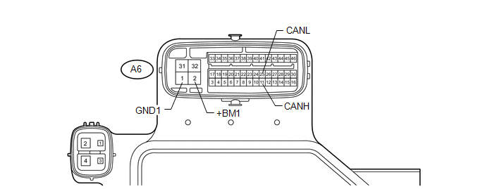
(a) Disconnect the A6 skid control ECU (master cylinder solenoid) connector.
(b) Measure the resistance according to the value(s) in the table below.
|
Terminal No. (Symbol) |
Wiring Color |
Switch Condition |
Specified Condition |
|---|---|---|---|
|
A6-11 (CANH) - A6-25 (CANL) |
B - W |
Ignition switch off |
54 to 69 Ω |
|
A6-11 (CANH) - A6-1 (GND1) |
B - W-B |
Ignition switch off |
200 Ω or higher |
|
A6-25 (CANL) - A6-1 (GND1) |
W - W-B |
Ignition switch off |
200 Ω or higher |
|
A6-11 (CANH) - A6-2 (+BM1) |
B - B |
Ignition switch off |
6 kΩ or higher |
|
A6-25 (CANL) - A6-2 (+BM1) |
W - B |
Ignition switch off |
6 kΩ or higher |
8. CHECK AIR CONDITIONING AMPLIFIER ASSEMBLY
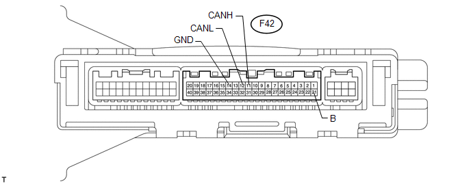
(a) Disconnect the F42 air conditioning amplifier assembly connector.
(b) Measure the resistance according to the value(s) in the table below.
|
Terminal No. (Symbol) |
Wiring Color |
Switch Condition |
Specified Condition |
|---|---|---|---|
|
F42-11 (CANH) - F42-12 (CANL) |
B - W |
Ignition switch off |
54 to 69 Ω |
|
F42-11 (CANH) - F42-14 (GND) |
B - W-B |
Ignition switch off |
200 Ω or higher |
|
F42-12 (CANL) - F42-14 (GND) |
W - W-B |
Ignition switch off |
200 Ω or higher |
|
F42-11 (CANH) - F42-21 (B) |
B - V |
Ignition switch off |
6 kΩ or higher |
|
F42-12 (CANL) - F42-21 (B) |
W - V |
Ignition switch off |
6 kΩ or higher |
9. CHECK STABILIZER CONTROL ECU (w/ Kinetic Dynamic Suspension System)
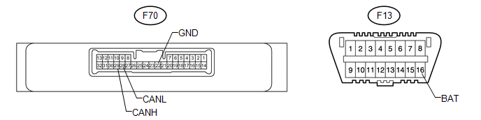
(a) Disconnect the F70 stabilizer control ECU connector.
(b) Measure the resistance according to the value(s) in the table below.
|
Terminal No. (Symbol) |
Wiring Color |
Switch Condition |
Specified Condition |
|---|---|---|---|
|
F70-29 (CANH) - F70-28 (CANL) |
P - W |
Ignition switch off |
54 to 69 Ω |
|
F70-29 (CANH) - F70-22 (GND) |
P - W-B |
Ignition switch off |
200 Ω or higher |
|
F70-28 (CANL) - F70-22 (GND) |
W - W-B |
Ignition switch off |
200 Ω or higher |
|
F70-29 (CANH) - F13-16 (BAT) |
P - GR |
Ignition switch off |
6 kΩ or higher |
|
F70-28 (CANL) - F13-16 (BAT) |
W - GR |
Ignition switch off |
6 kΩ or higher |
10. CHECK COMBINATION METER ASSEMBLY
 Text in Illustration
|
*a |
for V1 Bus |
*b |
for MS Bus (w/ Seat Position Memory) |
(a) Disconnect the F14 combination meter assembly connector.
(b) Measure the resistance according to the value(s) in the table below.
for V1 Bus|
Terminal No. (Symbol) |
Wiring Color |
Switch Condition |
Specified Condition |
|---|---|---|---|
|
F14-1 (CANH) - F14-2 (CANL) |
L - W |
Ignition switch off |
108 to 132 Ω |
|
F14-1 (CANH) - F14-20 (E1) |
L - W-B |
Ignition switch off |
200 Ω or higher |
|
F14-2 (CANL) - F14-20 (E1) |
W - W-B |
Ignition switch off |
200 Ω or higher |
|
F14-1 (CANH) - F14-15 (B) |
L - L |
Ignition switch off |
6 kΩ or higher |
|
F14-2 (CANL) - F14-15 (B) |
W - L |
Ignition switch off |
6 kΩ or higher |
|
Terminal No. (Symbol) |
Wiring Color |
Switch Condition |
Specified Condition |
|---|---|---|---|
|
F14-23 (MSCH) - F14-24 (MSCL) |
LG - W |
Ignition switch off |
108 to 132 Ω |
|
F14-23 (MSCH) - F14-20 (E1) |
LG - W-B |
Ignition switch off |
200 Ω or higher |
|
F14-24 (MSCL) - F14-20 (E1) |
W - W-B |
Ignition switch off |
200 Ω or higher |
|
F14-23 (MSCH) - F14-15 (B) |
LG - L |
Ignition switch off |
6 kΩ or higher |
|
F14-24 (MSCL) - F14-15 (B) |
W - L |
Ignition switch off |
6 kΩ or higher |
11. CHECK AIRBAG SENSOR ASSEMBLY
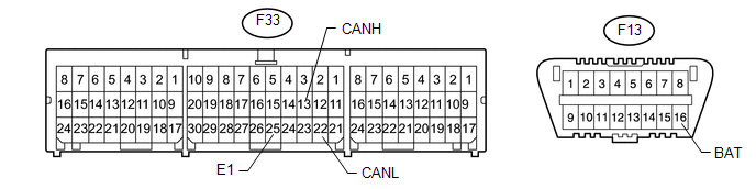
(a) Disconnect the F33 airbag sensor assembly connector.
(b) Measure the resistance according to the value(s) in the table below.
|
Terminal No. (Symbol) |
Wiring Color |
Switch Condition |
Specified Condition |
|---|---|---|---|
|
F33-13 (CANH) - F33-22 (CANL) |
Y - W |
Ignition switch off |
54 to 69 Ω |
|
F33-13 (CANH) - F33-25 (E1) |
Y - W-B |
Ignition switch off |
200 Ω or higher |
|
F33-22 (CANL) - F33-25 (E1) |
W - W-B |
Ignition switch off |
200 Ω or higher |
|
F33-13 (CANH) - F13-16 (BAT) |
Y - GR |
Ignition switch off |
6 kΩ or higher |
|
F33-22 (CANL) - F13-16 (BAT) |
W - GR |
Ignition switch off |
6 kΩ or higher |
12. CHECK STEERING ANGLE SENSOR (SPIRAL CABLE SUB-ASSEMBLY)
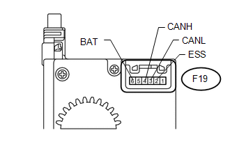
(a) Disconnect the F19 steering angle sensor (spiral cable sub-assembly) connector.
(b) Measure the resistance according to the value(s) in the table below.
|
Terminal No. (Symbol) |
Wiring Color |
Switch Condition |
Specified Condition |
|---|---|---|---|
|
F19-4 (CANH) - F19-3 (CANL) |
G - W |
Ignition switch off |
54 to 69 Ω |
|
F19-4 (CANH) - F19-2 (ESS) |
G - W-B |
Ignition switch off |
200 Ω or higher |
|
F19-3 (CANL) - F19-2 (ESS) |
W - W-B |
Ignition switch off |
200 Ω or higher |
|
F19-4 (CANH) - F19-6 (BAT) |
G - L |
Ignition switch off |
6 kΩ or higher |
|
F19-3 (CANL) - F19-6 (BAT) |
W - L |
Ignition switch off |
6 kΩ or higher |
13. CHECK NAVIGATION RECEIVER ASSEMBLY (for Navigation Receiver Type)
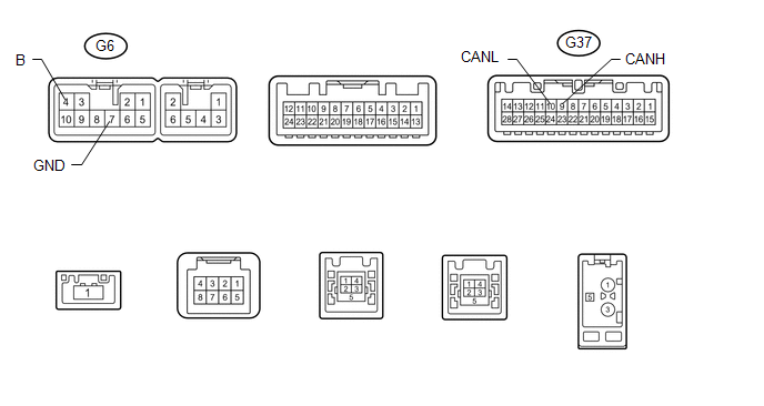
(a) Disconnect the G6 and G37 navigation receiver assembly connectors.
(b) Measure the resistance according to the value(s) in the table below.
|
Terminal No. (Symbol) |
Wiring Color |
Switch Condition |
Specified Condition |
|---|---|---|---|
|
G37-9 (CANH) - G37-10 (CANL) |
P - W |
Ignition switch off |
54 to 69 Ω |
|
G37-9 (CANH) - G6-7 (GND) |
P - BR |
Ignition switch off |
200 Ω or higher |
|
G37-10 (CANL) - G6-7 (GND) |
W - BR |
Ignition switch off |
200 Ω or higher |
|
G37-9 (CANH) - G6-4 (B) |
P - SB |
Ignition switch off |
6 kΩ or higher |
|
G37-10 (CANL) - G6-4 (B) |
W - SB |
Ignition switch off |
6 kΩ or higher |
14. CHECK YAW RATE SENSOR ASSEMBLY
(a) Disconnect the F36 yaw rate sensor assembly connector.
(b) Measure the resistance according to the value(s) in the table below.
|
Terminal No. (Symbol) |
Wiring Color |
Switch Condition |
Specified Condition |
|---|---|---|---|
|
F36-3 (CANH) - F36-2 (CANL) |
R - W |
Ignition switch off |
54 to 69 Ω |
|
F36-3 (CANH) - F36-1 (GND) |
R - W-B |
Ignition switch off |
200 Ω or higher |
|
F36-2 (CANL) - F36-1 (GND) |
W - W-B |
Ignition switch off |
200 Ω or higher |
|
F36-3 (CANH) - F13-16 (BAT) |
R - GR |
Ignition switch off |
6 kΩ or higher |
|
F36-2 (CANL) - F13-16 (BAT) |
W - GR |
Ignition switch off |
6 kΩ or higher |
15. CHECK POWER STEERING ECU ASSEMBLY
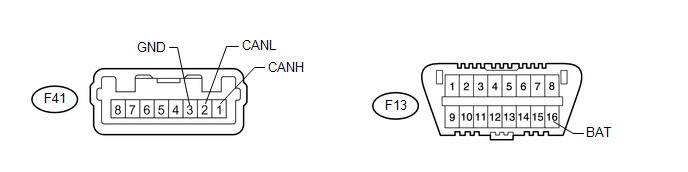
(a) Disconnect the F41 power steering ECU assembly connector.
(b) Measure the resistance according to the value(s) in the table below.
|
Terminal No. (Symbol) |
Wiring Color |
Switch Condition |
Specified Condition |
|---|---|---|---|
|
F41-1 (CANH) - F41-2 (CANL) |
L - W |
Ignition switch off |
54 to 69 Ω |
|
F41-1 (CANH) - F41-3 (GND) |
L - W-B |
Ignition switch off |
200 Ω or higher |
|
F41-2 (CANL) - F41-3 (GND) |
W - W-B |
Ignition switch off |
200 Ω or higher |
|
F41-1 (CANH) - F13-16 (BAT) |
L - GR |
Ignition switch off |
6 kΩ or higher |
|
F41-2 (CANL) - F13-16 (BAT) |
W - GR |
Ignition switch off |
6 kΩ or higher |
16. CHECK FOUR WHEEL DRIVE CONTROL ECU (for 4WD)
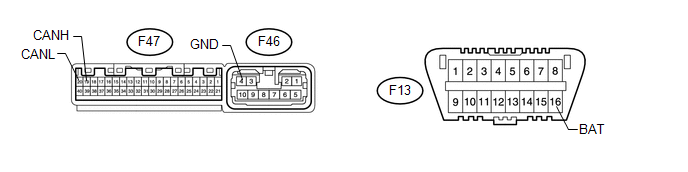
(a) Disconnect the F47 and F46 four wheel drive control ECU connectors.
(b) Measure the resistance according to the value(s) in the table below.
|
Terminal No. (Symbol) |
Wiring Color |
Switch Condition |
Specified Condition |
|---|---|---|---|
|
F47-19 (CANH) - F47-20 (CANL) |
G - W |
Ignition switch off |
54 to 69 Ω |
|
F47-19 (CANH) - F46-4 (GND) |
G - W-B |
Ignition switch off |
200 Ω or higher |
|
F47-20 (CANL) - F46-4 (GND) |
W - W-B |
Ignition switch off |
200 Ω or higher |
|
F47-19 (CANH) - F13-16 (BAT) |
G - GR |
Ignition switch off |
6 kΩ or higher |
|
F47-20 (CANL) - F13-16 (BAT) |
W - GR |
Ignition switch off |
6 kΩ or higher |
17. CHECK POWER MANAGEMENT CONTROL ECU (w/ Smart Key System)
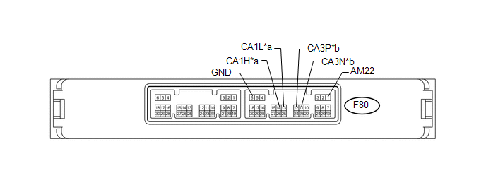 Text in Illustration
|
*a |
for V1 Bus |
*b |
for Power Management Bus |
(a) Disconnect the F80 power management control ECU connector.
(b) Measure the resistance according to the value(s) in the table below.
for V1 Bus|
Terminal No. (Symbol) |
Wiring Color |
Switch Condition |
Specified Condition |
|---|---|---|---|
|
F80-14 (CA1H) - F80-13 (CA1L) |
P - W |
Ignition switch off |
54 to 69 Ω |
|
F80-14 (CA1H) - F80-6 (GND) |
P - W-B |
Ignition switch off |
200 Ω or higher |
|
F80-13 (CA1L) - F80-6 (GND) |
W - W-B |
Ignition switch off |
200 Ω or higher |
|
F80-14 (CA1H) - F80-1 (AM22) |
P - B |
Ignition switch off |
6 kΩ or higher |
|
F80-13 (CA1L) - F80-1 (AM22) |
W - B |
Ignition switch off |
6 kΩ or higher |
|
Terminal No. (Symbol) |
Wiring Color |
Switch Condition |
Specified Condition |
|---|---|---|---|
|
F80-12 (CA3P) - F80-11 (CA3N) |
L - W |
Ignition switch off |
108 to 132 Ω |
|
F80-12 (CA3P) - F80-6 (GND) |
L - W-B |
Ignition switch off |
200 Ω or higher |
|
F80-11 (CA3N) - F80-6 (GND) |
W - W-B |
Ignition switch off |
200 Ω or higher |
|
F80-12 (CA3P) - F80-1 (AM22) |
L - B |
Ignition switch off |
6 kΩ or higher |
|
F80-11 (CA3N) - F80-1 (AM22) |
W - B |
Ignition switch off |
6 kΩ or higher |
18. CHECK CERTIFICATION ECU (SMART KEY ECU ASSEMBLY) (w/ Smart Key System)
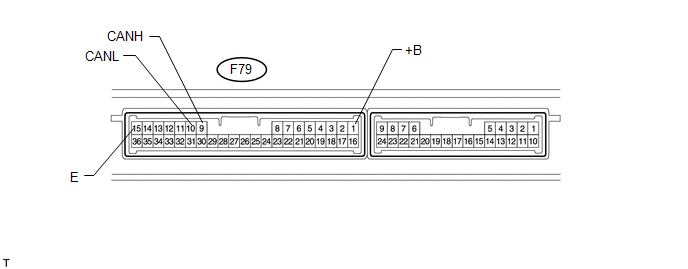
(a) Disconnect the F79 certification ECU (smart key ECU assembly) connector.
(b) Measure the resistance according to the value(s) in the table below.
|
Terminal No. (Symbol) |
Wiring Color |
Switch Condition |
Specified Condition |
|---|---|---|---|
|
F79-9 (CANH) - F79-10 (CANL) |
Y - W |
Ignition switch off |
54 to 69 Ω |
|
F79-9 (CANH) - F79-15 (E) |
Y - W-B |
Ignition switch off |
200 Ω or higher |
|
F79-10 (CANL) - F79-15 (E) |
W - W-B |
Ignition switch off |
200 Ω or higher |
|
F79-9 (CANH) - F79-1 (+B) |
Y - V |
Ignition switch off |
6 kΩ or higher |
|
F79-10 (CANL) - F79-1 (+B) |
W - V |
Ignition switch off |
6 kΩ or higher |
19. CHECK DRIVE MONITOR SWITCH (w/ CRAWL Control)
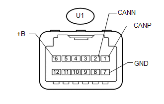
(a) Disconnect the U1 drive monitor switch connector.
(b) Measure the resistance according to the value(s) in the table below.
|
Terminal No. (Symbol) |
Wiring Color |
Switch Condition |
Specified Condition |
|---|---|---|---|
|
U1-1 (CANP) - U1-2 (CANN) |
B - W |
Ignition switch off |
108 to 132 Ω |
|
U1-1 (CANP) - U1-7 (GND) |
B - W-B |
Ignition switch off |
200 Ω or higher |
|
U1-2 (CANN) - U1-7 (GND) |
W - W-B |
Ignition switch off |
200 Ω or higher |
|
U1-1 (CANP) - U1-6 (+B) |
B - L |
Ignition switch off |
6 kΩ or higher |
|
U1-2 (CANN) - U1-6 (+B) |
W - L |
Ignition switch off |
6 kΩ or higher |
20. CHECK RADIO AND DISPLAY RECEIVER ASSEMBLY (for Radio and Display Receiver Type)
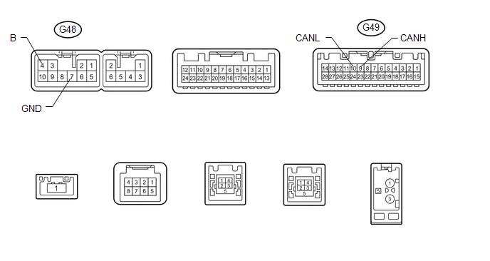
(a) Disconnect the G48 and G49 radio and display receiver assembly connectors.
(b) Measure the resistance according to the value(s) in the table below.
|
Terminal No. (Symbol) |
Wiring Color |
Switch Condition |
Specified Condition |
|---|---|---|---|
|
G49-9 (CANH) - G49-10 (CANL) |
P - W |
Ignition switch off |
54 to 69 Ω |
|
G49-9 (CANH) - G48-7 (GND) |
P - BR |
Ignition switch off |
200 Ω or higher |
|
G49-10 (CANL) - G48-7 (GND) |
W - BR |
Ignition switch off |
200 Ω or higher |
|
G49-9 (CANH) - G48-4 (B) |
P - SB |
Ignition switch off |
6 kΩ or higher |
|
G49-10 (CANL) - G48-4 (B) |
W - SB |
Ignition switch off |
6 kΩ or higher |
21. CHECK FRONT POWER SEAT SWITCH LH (w/ Seat Position Memory)

(a) Disconnect the b18 and b19 front power seat switch LH connectors.
(b) Measure the resistance according to the value(s) in the table below.
|
Terminal No. (Symbol) |
Wiring Color |
Switch Condition |
Specified Condition |
|---|---|---|---|
|
b19-8 (CANP) - b19-7 (CANN) |
L - W |
Ignition switch off |
54 to 69 Ω |
|
b19-8 (CANP) - b18-2 (GND) |
L - W-B |
Ignition switch off |
200 Ω or higher |
|
b19-7 (CANN) - b18-2 (GND) |
W - W-B |
Ignition switch off |
200 Ω or higher |
|
b19-8 (CANP) - b18-7 (B) |
L - W |
Ignition switch off |
6 kΩ or higher |
|
b19-7 (CANN) - b18-7 (B) |
W - W |
Ignition switch off |
6 kΩ or higher |
 Problem Symptoms Table
PROBLEM SYMPTOMS TABLE
HINT:
Use the table below to help determine the cause of problem symptoms. If multiple
suspected areas are listed, the potential causes of the symptoms are listed in order
...
 Diagnosis System
DIAGNOSIS SYSTEM
1. BUS CHECK
(a) Select "CAN Bus Check" from "System Select".
2. CHECK FOR INSTALLED SYSTEMS (ECUS AND SENSORS) THAT USE CAN COMMUNICATION
(a) The systems (ECU ...
Other materials about Toyota 4Runner:
Back Door ECU Communication Stop (B1287)
DESCRIPTION
This DTC is stored when LIN communication between the multiplex network door
ECU (back door P/W) and main body ECU (multiplex network body ECU) stops for 10
seconds or more.
DTC Code
DTC Detection Condition
Tr ...
Removal
REMOVAL
PROCEDURE
1. DISCONNECT CABLE FROM NEGATIVE BATTERY TERMINAL
CAUTION:
Wait at least 90 seconds after disconnecting the cable from the negative (-)
battery terminal to disable the SRS system.
NOTICE:
When disconnecting the cable, some systems ne ...

0.0304