Toyota 4Runner: Speed Signal Malfunction (B15C2)
DESCRIPTION
The navigation receiver assembly receives a vehicle speed signal from the combination meter assembly and information from the navigation antenna assembly, and then adjusts the vehicle position.
The navigation receiver assembly stores this DTC when the difference between the speed information that the navigation antenna assembly receives and the SPD pulse received from the combination meter assembly becomes large.
HINT:
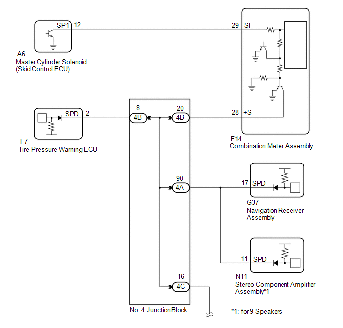
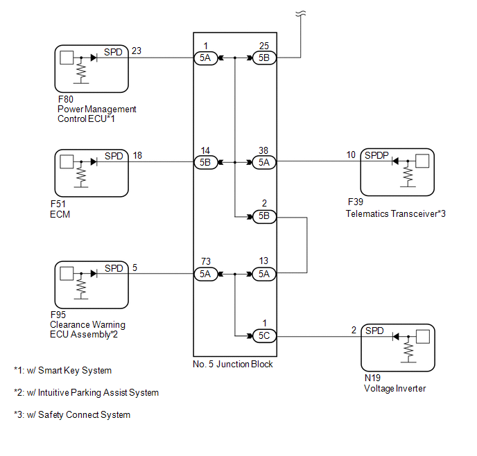
- A voltage of 12 V or 5 V is output from each ECU and then input to the combination meter assembly. The signal is changed to a pulse signal at the transistor in the combination meter assembly. Each ECU controls the respective systems based on the pulse signal.
- If a short occurs in any of the ECUs or in the wire harness connected to an ECU, all systems in the diagram below will not operate normally.
|
DTC No. |
DTC Detection Condition |
Trouble Area |
|---|---|---|
|
B15C2 |
A difference between the GPS speed and SPD pulse is detected. |
|
WIRING DIAGRAM
CAUTION / NOTICE / HINT
NOTICE:
After replacing the navigation receiver assembly of vehicles subscribed to pay-type satellite radio broadcasts, registration of the XM radio ID is necessary.
PROCEDURE
|
1. |
CHECK VEHICLE SENSOR (OPERATION CHECK) |
|
(a) Enter the "System Sensors Check" screen. Refer to Check GPS and Vehicle
Sensors in Operation Check (See page |
|
.gif) ).
).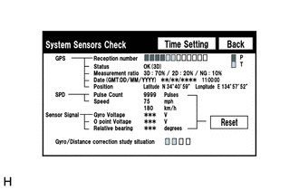
(b) While driving the vehicle, compare the value of "Speed" to the reading on the speedometer. Check if these readings are almost equal.
OK:
The readings are equal or almost equal.
| OK | .gif) |
REPLACE NAVIGATION RECEIVER ASSEMBLY |
|
.gif)
|
2. |
INSPECT COMBINATION METER ASSEMBLY (OUTPUT WAVEFORM) |
|
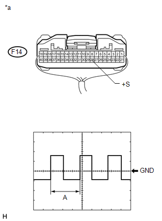
(a) Check the output waveform. (1) Remove the combination meter assembly with the connector(s) still connected. (2) Connect an oscilloscope to terminal F14-28 (+S) and body ground. (3) Turn the ignition switch to ON. (4) Turn a wheel slowly. (5) Check the signal waveform according to the condition(s) in the table below.
OK: The waveform is similar to that shown in the illustration. HINT: When the system is functioning normally, one wheel revolution generates 4 pulses. As the vehicle speed increases, the width indicated by (A) in the illustration narrows. Text in Illustration
|
|
| NG | |
GO TO METER / GAUGE SYSTEM |
|
|
3. |
INSPECT NAVIGATION RECEIVER ASSEMBLY (OUTPUT WAVEFORM) |
|
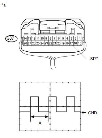
(a) Check the output waveform. (1) Remove the navigation receiver assembly with the connector(s) still connected. (2) Connect an oscilloscope to terminal G37-17 (SPD) and body ground. (3) Turn the ignition switch to ON. (4) Turn a wheel slowly. (5) Check the signal waveform according to the condition(s) in the table below.
OK: The waveform is similar to that shown in the illustration. HINT: When the system is functioning normally, one wheel revolution generates 4 pulses. As the vehicle speed increases, the width indicated by (A) in the illustration narrows. Text in Illustration
|
|
| OK | |
REPLACE NAVIGATION RECEIVER ASSEMBLY |
|
|
4. |
CHECK HARNESS AND CONNECTOR (COMBINATION METER ASSEMBLY - NO. 4 JUNCTION BLOCK) |
(a) Disconnect the F14 combination meter assembly connector.
(b) Disconnect the 4B No. 4 junction block connector.
(c) Measure the resistance according to the value(s) in the table below.
Standard Resistance:
|
Tester Connection |
Condition |
Specified Condition |
|---|---|---|
|
F14-28 (+S) - 4B-20 |
Always |
Below 1 Ω |
| NG | |
REPAIR OR REPLACE HARNESS AND CONNECTOR (COMBINATION METER ASSEMBLY - NO. 4 JUNCTION BLOCK) |
|
|
5. |
CHECK HARNESS AND CONNECTOR (NAVIGATION RECEIVER ASSEMBLY - NO. 4 JUNCTION BLOCK) |
(a) Disconnect the G37 navigation receiver assembly connector.
(b) Disconnect the 4A No. 4 junction block connector.
(c) Measure the resistance according to the value(s) in the table below.
Standard Resistance:
|
Tester Connection |
Condition |
Specified Condition |
|---|---|---|
|
G37-17 (SPD) - 4A-90 |
Always |
Below 1 Ω |
| OK | |
REPAIR OR REPLACE HARNESS OR CONNECTOR (NO. 4 JUNCTION BLOCK) |
| NG | |
REPAIR OR REPLACE HARNESS OR CONNECTOR (NAVIGATION RECEIVER ASSEMBLY - NO. 4 JUNCTION BLOCK) |
 GPS Antenna Connection Malfunction(short) (B15C0,B15C1)
DESCRIPTION
These DTCs are stored when a malfunction occurs in the navigation antenna assembly.
DTC No.
DTC Detection Condition
Trouble Area
B15C0
...
 Speaker Output Short (B15C3)
DESCRIPTION
This DTC is stored when a malfunction occurs in the speakers.
DTC No.
DTC Detection Condition
Trouble Area
B15C3
A short is d ...
Other materials about Toyota 4Runner:
Turn signal lever
The turn signal lever can be used to show the following intentions of the
driver:
1. Right turn 2. Left turn 3. Lane change to the right (push and hold the
lever partway) The right hand signals will flash until you release the lever.
4. Lane change to ...
Initialization
INITIALIZATION
1. INITIALIZE SLIDING ROOF DRIVE GEAR SUB-ASSEMBLY
NOTICE:
Before starting this operation, make sure that the guide rails are not
deformed and there is no foreign object on the guide rails.
When the sliding roof glass is adjus ...

0.0068