Toyota 4Runner: Speed Sensor
Components
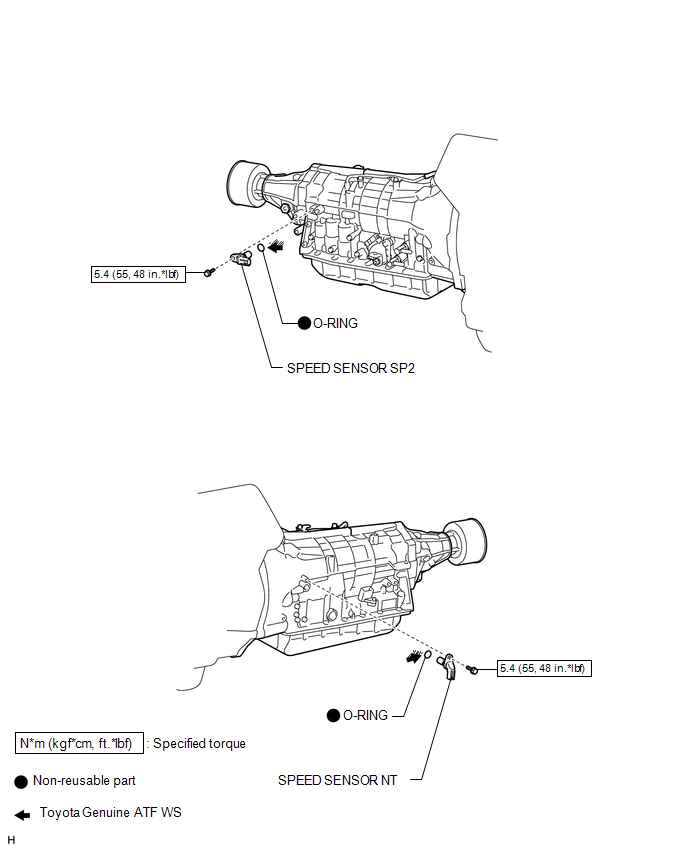
COMPONENTS
ILLUSTRATION
Removal
REMOVAL
PROCEDURE
1. REMOVE SPEED SENSOR NT
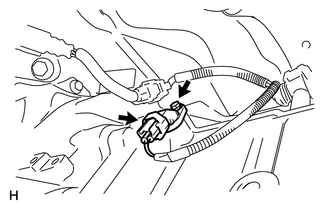
(a) Disconnect the sensor connector.
(b) Remove the bolt and sensor.
(c) Remove the O-ring from the sensor.
2. REMOVE SPEED SENSOR SP2
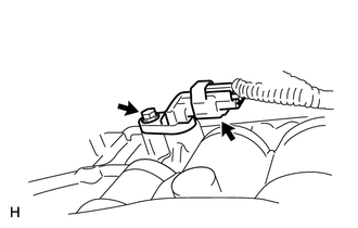
(a) Disconnect the sensor connector.
(b) Remove the bolt and sensor.
(c) Remove the O-ring from the sensor.
Inspection
INSPECTION
PROCEDURE
1. INSPECT SPEED SENSOR NT AND SP2
.png)
(a) Measure the resistance according to the value(s) in the table below.
Standard Resistance:
|
Tester Connection |
Condition |
Specified Condition |
|---|---|---|
|
1 - 2 |
20°C (68°F) |
560 to 680 Ω |
|
*a |
Component without harness connected (Speed Sensor) |
If the result is not as specified, replace the sensor.
Installation
INSTALLATION
PROCEDURE
1. INSTALL SPEED SENSOR SP2
(a) Coat a new O-ring with ATF and install it to the sensor.
(b) Install the sensor with the bolt.
Torque:
5.4 N·m {55 kgf·cm, 48 in·lbf}
(c) Connect the sensor connector.
2. INSTALL SPEED SENSOR NT
(a) Coat a new O-ring with ATF and install it to the sensor.
(b) Install the sensor with the bolt.
Torque:
5.4 N·m {55 kgf·cm, 48 in·lbf}
(c) Connect the sensor connector.
 Reassembly
REASSEMBLY
PROCEDURE
1. INSTALL SHIFT LOCK CONTROL ECU SUB-ASSEMBLY
(a) Attach the 3 claws to install the shift lock control ECU to the transmission
floor shift.
(b) Connect the shift lock solen ...
 Torque Converter Clutch And Drive Plate
Inspection
INSPECTION
PROCEDURE
1. INSPECT TORQUE CONVERTER CLUTCH ASSEMBLY
(a) Inspect the 1-way clutch.
(1) Install SST to the inner race of the 1-way clutch.
SST: 09350-32014
09351-32020 ...
Other materials about Toyota 4Runner:
Removal
REMOVAL
PROCEDURE
1. REMOVE JACK BOX HOLE COVER
2. REMOVE REAR QUARTER PANEL MUDGUARD LH
3. REMOVE REAR QUARTER PANEL MUDGUARD RH
HINT:
Use the same procedure as for the LH side.
4. REMOVE REAR BUMPER COVER
5. REMOVE NO. 3 FLOOR WIRE
6. RE ...
Off-road vehicle feature
• Specific design characteristics give it a higher center of gravity than
ordinary passenger cars. This vehicle design feature causes this type of vehicle
to be more likely to rollover. And, utility vehicles have a significantly higher
rollover rate th ...

0.0271