Toyota 4Runner: Speed Signal Circuit
DESCRIPTION
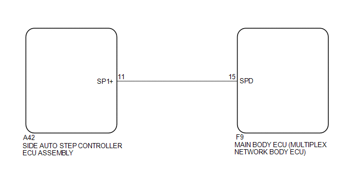
The vehicle speed signal consists of pulses sent to the side auto step controller ECU assembly from the main body ECU (multiplex network body ECU).
WIRING DIAGRAM
PROCEDURE
|
1. |
INSPECT MAIN BODY ECU (MULTIPLEX NETWORK BODY ECU) |
(a) Measure the voltage according to the value(s) in the table below.
Standard Voltage:
|
Tester Connection |
Condition |
Specified Condition |
|---|---|---|
|
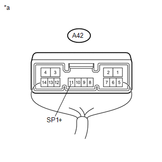
A42-11 (SP1+) - Body ground |
Vehicle speed at lower than 8 km/h (5 mph) |
11 to 14 V |
|
Vehicle speed at 8 km/h (5 mph) or more |
Below 1 V |
|
*a |
Component with harness connected (Side Auto Step Controller ECU Assembly) |
|
Result |
Proceed to |
|---|---|
|
NG |
A |
|
OK |
B |
| B | .gif) |
REPLACE SIDE AUTO STEP CONTROLLER ECU ASSEMBLY |
|
.gif)
|
2. |
CHECK HARNESS AND CONNECTOR (SIDE AUTO STEP ECU - MAIN BODY ECU) |
(a) Disconnect the A42 side auto step controller ECU assembly connector.
(b) Disconnect the F9 main body ECU (multiplex network body ECU) connector.
(c) Measure the resistance according to the value(s) in the table below.
Standard Resistance (Check for Open):
|
Tester Connection |
Condition |
Specified Condition |
|---|---|---|
|
A42-11 (SP1+) - F9-15 (SPD) |
Always |
Below 1 Ω |
Standard Resistance (Check for Short):
|
Tester Connection |
Condition |
Specified Condition |
|---|---|---|
|
A42-11 (SP1+) - Body ground |
Always |
10 kΩ or higher |
| OK | |
PROCEED TO NEXT SUSPECTED AREA SHOWN IN PROBLEM SYMPTOMS TABLE |
| NG | |
REPAIR OR REPLACE HARNESS OR CONNECTOR |
 Door Courtesy Switch Circuit
DESCRIPTION
The side auto step controller ECU assembly receives the door open/closed signal
from each door courtesy light switch via the side auto step switch assembly.
WIRING DIAGRAM
CAUTION / ...

Other materials about Toyota 4Runner:
How To Proceed With Troubleshooting
CAUTION / NOTICE / HINT
HINT:
Use the following procedures to troubleshoot the intuitive parking assist system.
PROCEDURE
1.
VEHICLE BROUGHT TO WORKSHOP
NEXT
...
Front Passenger Side Solar Sensor Short Circuit (B14A3)
DESCRIPTION
The automatic light control sensor (solar sensor), which is installed on the
upper side of the instrument panel, detects sunlight and controls the air conditioning
in auto mode. The output current from the solar sensor varies according to th ...

0.0272