Toyota 4Runner: Steering Knuckle(for 2wd)
Components
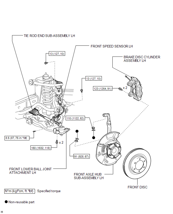
COMPONENTS
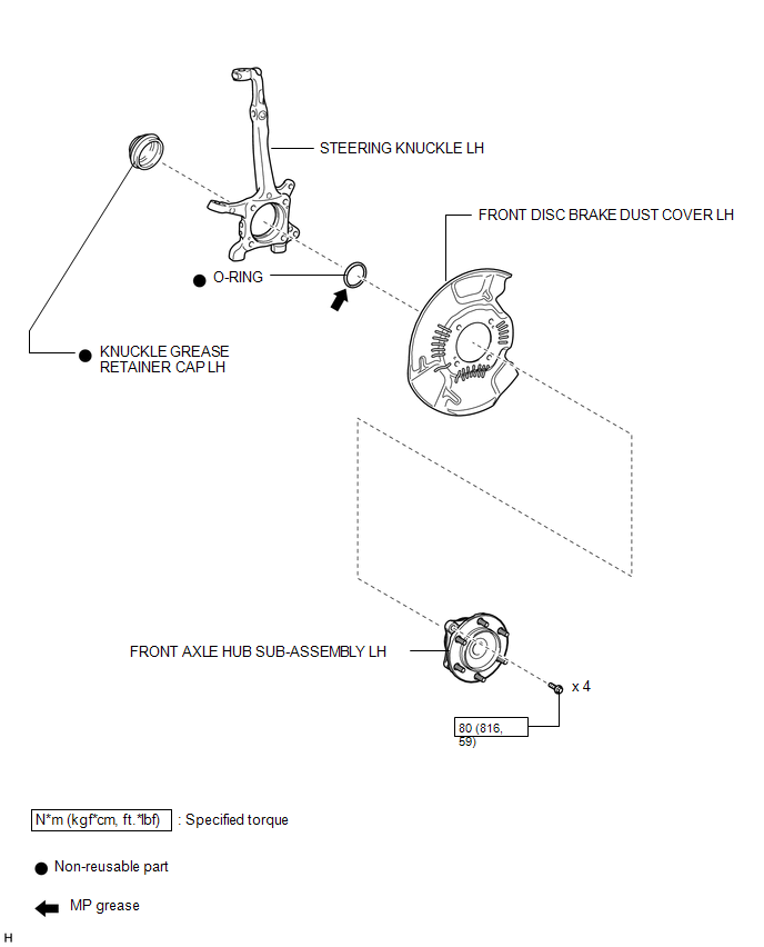
ILLUSTRATION
ILLUSTRATION
Removal
REMOVAL
CAUTION / NOTICE / HINT
HINT:
- Use the same procedure for the RH and LH sides.
- The procedure listed below is for the LH side.
PROCEDURE
1. DISCONNECT CABLE FROM NEGATIVE BATTERY TERMINAL
NOTICE:
When disconnecting the cable, some systems need to be initialized after the cable
is reconnected (See page .gif) ).
).
2. REMOVE FRONT SPEED SENSOR LH
3. REMOVE FRONT AXLE HUB SUB-ASSEMBLY LH
(a) Remove the front axle hub (See page ).
4. DISCONNECT TIE ROD END SUB-ASSEMBLY LH
5. DISCONNECT FRONT LOWER BALL JOINT ATTACHMENT LH
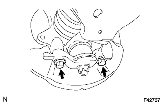
(a) Remove the 2 bolts and disconnect the front lower ball joint attachment from the axle.
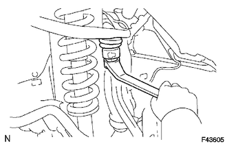
6. REMOVE STEERING KNUCKLE LH
(a) Support the front suspension lower arm LH with a jack.
(b) Remove the clip and nut.
|
(c) Using SST, disconnect the upper ball joint from the steering knuckle. SST: 09628-62011 NOTICE: Do not the damage the ball joint dust cover. |
|
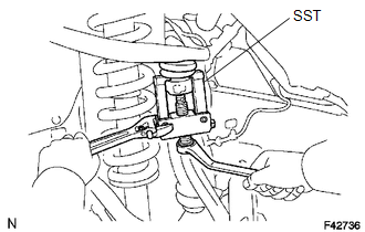
(d) Remove the steering knuckle.
Disassembly
DISASSEMBLY
PROCEDURE
1. REMOVE KNUCKLE GREASE RETAINER CAP LH
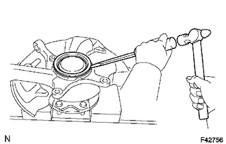
(a) Using a screwdriver and hammer, remove the knuckle grease retainer cap.
Reassembly
REASSEMBLY
PROCEDURE
1. INSTALL KNUCKLE GREASE RETAINER CAP LH
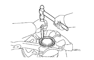
(a) Using a brass bar and a hammer, install a new retainer cap.
NOTICE:
Do not damage the knuckle grease retainer cap.
Installation
INSTALLATION
CAUTION / NOTICE / HINT
HINT:
- Use the same procedure for the RH and LH sides.
- The procedure listed below is for the LH side.
PROCEDURE
1. INSTALL STEERING KNUCKLE LH
(a) Install the steering knuckle to the front suspension upper arm with the nut.
Torque:
110 N·m {1122 kgf·cm, 82 ft·lbf}
(b) Install a new cotter pin.
2. CONNECT FRONT LOWER BALL JOINT ATTACHMENT LH
(a) Connect the front lower ball joint attachment and install the 2 bolts.
Torque:
160 N·m {1632 kgf·cm, 118 ft·lbf}
3. INSTALL TIE ROD END SUB-ASSEMBLY LH
.gif)
4. INSTALL FRONT AXLE HUB SUB-ASSEMBLY LH
(a) Install the front axle hub (See page ).
5. INSTALL FRONT SPEED SENSOR LH
6. CONNECT CABLE TO NEGATIVE BATTERY TERMINAL
NOTICE:
When disconnecting the cable, some systems need to be initialized after the cable
is reconnected (See page ).
7. INSTALL FRONT WHEEL
Torque:
for aluminum wheel :
103 N·m {1050 kgf·cm, 76 ft·lbf}
for steel wheel :
112 N·m {1142 kgf·cm, 83 ft·lbf}
8. INSPECT AND ADJUST FRONT WHEEL ALIGNMENT
(a) Inspect and adjust the front wheel alignment (See page
).
9. INSPECT SPEED SENSOR SIGNAL
(a) Inspect the speed sensor signal (See page
).
 Rear Differential Lock Position Switch
Components
COMPONENTS
ILLUSTRATION
Inspection
INSPECTION
PROCEDURE
1. INSPECT REAR DIFFERENTIAL LOCK POSITION SWITCH
(a) Measure the resistance according to the value(s) in the ...
 Steering Knuckle(for 4wd)
Components
COMPONENTS
ILLUSTRATION
ILLUSTRATION
Removal
REMOVAL
CAUTION / NOTICE / HINT
HINT:
Use the same procedure for the RH and LH sides.
The procedure listed below is ...
Other materials about Toyota 4Runner:
Data List / Active Test
DATA LIST / ACTIVE TEST
1. DATA LIST
HINT:
Using the Techstream to read the Data List allows the values or states of switches,
sensors, actuators and other items to be read without removing any parts. This non-intrusive
inspection can be very useful bec ...
Inspection
INSPECTION
PROCEDURE
1. INSPECT TIRES
(a) Check the tires for wear and proper inflation pressure.
Cold Tire Inflation Pressure (Unloaded Vehicle):
Tire Size
Vehicle Model
Front
kPa (kgf/cm2, psi)
Rear
kPa ...

0.0065