Toyota 4Runner: Steering Knuckle(for 4wd)
Components
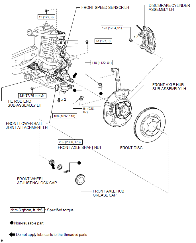
COMPONENTS
ILLUSTRATION
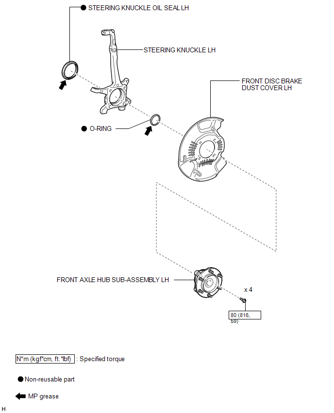
ILLUSTRATION
Removal
REMOVAL
CAUTION / NOTICE / HINT
HINT:
- Use the same procedure for the RH and LH sides.
- The procedure listed below is for the LH side.
PROCEDURE
1. DISCONNECT CABLE FROM NEGATIVE BATTERY TERMINAL
NOTICE:
When disconnecting the cable, some systems need to be initialized after the cable
is reconnected (See page .gif) ).
).
2. REMOVE FRONT SPEED SENSOR LH
3. REMOVE FRONT AXLE HUB SUB-ASSEMBLY LH
(a) Remove the front axle hub (See page ).
4. DISCONNECT TIE ROD END SUB-ASSEMBLY LH
5. DISCONNECT FRONT LOWER BALL JOINT ATTACHMENT LH
.png)
(a) Remove the 2 bolts and disconnect the front lower ball joint attachment from the axle.
6. REMOVE STEERING KNUCKLE LH
(a) Support the front suspension lower arm LH with a jack.
(b) Remove the clip and nut.
|
(c) Using SST, disconnect the upper ball joint from the steering knuckle. SST: 09628-62011 NOTICE: Do not the damage the ball joint dust cover. |
|
.png)
(d) Remove the steering knuckle.
Disassembly
DISASSEMBLY
PROCEDURE
1. REMOVE STEERING KNUCKLE OIL SEAL LH
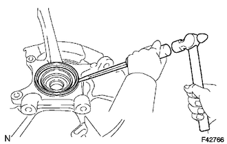
(a) Using a screwdriver and hammer, remove the steering knuckle oil seal.
Reassembly
REASSEMBLY
PROCEDURE
1. INSTALL STEERING KNUCKLE OIL SEAL LH
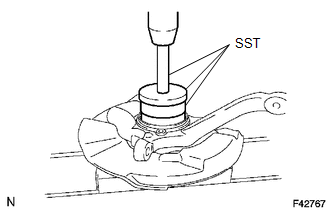
(a) Using SST and a press, install a new steering knuckle oil seal.
SST: 09527-17011
SST: 09950-70010
09951-07100
SST: 09951-01000
Installation
INSTALLATION
CAUTION / NOTICE / HINT
HINT:
- Use the same procedure for the RH and LH sides.
- The procedure listed below is for the LH side.
PROCEDURE
1. INSTALL STEERING KNUCKLE LH
.png)
(a) Install the steering knuckle to the front suspension upper arm with the nut.
Torque:
110 N·m {1122 kgf·cm, 82 ft·lbf}
(b) Install a new cotter pin.
2. INSTALL FRONT LOWER BALL JOINT ATTACHMENT LH
(a) Install the front lower ball joint attachment with the 2 bolts.
Torque:
160 N·m {1632 kgf·cm, 118 ft·lbf}
3. INSTALL TIE ROD END SUB-ASSEMBLY LH
.gif)
4. INSTALL FRONT AXLE HUB SUB-ASSEMBLY LH
(a) Install the front axle hub (See page ).
5. INSTALL FRONT SPEED SENSOR LH
6. CONNECT CABLE TO NEGATIVE BATTERY TERMINAL
NOTICE:
When disconnecting the cable, some systems need to be initialized after the cable
is reconnected (See page ).
7. INSTALL FRONT WHEEL
Torque:
for aluminum wheel :
103 N·m {1050 kgf·cm, 76 ft·lbf}
for steel wheel :
112 N·m {1142 kgf·cm, 83 ft·lbf}
8. INSPECT AND ADJUST FRONT WHEEL ALIGNMENT
(a) Inspect and adjust the front wheel alignment (See page
).
9. CHECK FRONT SPEED SENSOR
(a) Check the front speed sensor (See page ).
 Steering Knuckle(for 2wd)
Components
COMPONENTS
ILLUSTRATION
ILLUSTRATION
Removal
REMOVAL
CAUTION / NOTICE / HINT
HINT:
Use the same procedure for the RH and LH sides.
The procedure listed below is ...

Other materials about Toyota 4Runner:
Outside Vehicle
General Maintenance
GENERAL MAINTENANCE
CAUTION / NOTICE / HINT
Performing the following maintenance checks on the vehicle is the owner's
responsibility. The owner may perform the maintenance or take the vehicle
to a service center. Che ...
Front Speed Sensor RH Output Malfunction (C1413,C1275,C1276,C1414)
DESCRIPTION
Refer to DTCs C1401 and C1402 (See page ).
DTC Code
DTC Detection Condition
Trouble Area
C1413
C1414
One of the following condition is met:
An open in the sensor signa ...

0.0086